Max 8 Guitar Processor, Part 2
In the last article, we did a lot of setup - we got input/output handling in place and added a compressor to the processing chain as an example of an “effects module.” In this article, we will continue adding effects, including a dual overdrive module and a three-stage EQ/Filter module. With these additions we will further explore Max 8’s user interface options, as well as taking a look at some of the “tweaks” that make Max/MSP functions a little more guitar-faithful.
Adding an Overdrive Section
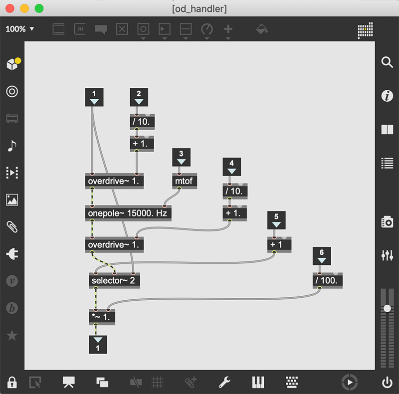
First up is an overdrive processor. I’ve found that the way to get the most variety with this sort of processor is to have two overdrive~ objects in series with a lowpass filter between them; the result is a controllable distortion/overdrive capable of some crazy variations. I have, again, encapsulated the overdrive functions in a subpatcher (in this case, called od_handler), which implements the dual overdrive~ setup, as well as a selector~ that provides the bypass functionality.

I’ve also added a level adjustment that allows us to tame the output levels post-overdrive~. This can be very handy since some of the more extreme overdrive settings can cause high levels (both real and perceived). I’ve also connected a meter~ object to the output of the subpatcher, giving me a way to eyeball the output of the compressor-overdrive pairing.
Adding an EQ/Filter
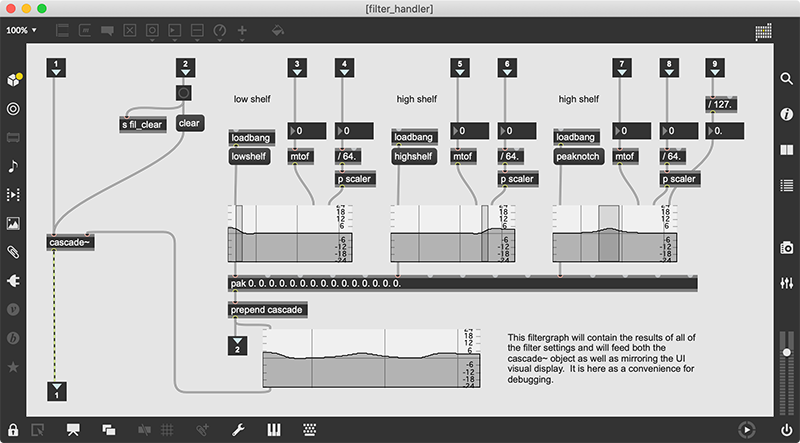
Next up is the creation of a EQ/Filter modules. This is going to use a cascade~ filter, which is a version of a biquad filter that takes lists of coefficients and creates a complex filter curve. In order to manage it using simplified controls, we will use a function of the filtergraph~ object that converts frequency/level combinations into biquad-type coefficients. By now, you should be able to see the design pattern in use: I create a subpatcher with the “guts” of the effect module, then attach controls for all of the variable parameters. Open the “filter_handler” subpatcher to examine the DSP functions used. Most of this subpatcher converts the incoming values into useful frequency and level values, then sends them into filtergraph~ objects. I could have just as easily used filtercoeff~ objects, but using the filtergraph~ lets me see the individual filter settings, helping me verify that the individual filter parameters are being set correctly. The coefficient outputs of the filtergraph~ objects are “pak’d” into a list of 15 floating point values (five for each filter), then prepended with the cascade message. This informs connected filter objects that more than one coefficient set will be used to create a complex filter.

This list is now sent to a cascade~ object, which implements the equivalent of serial biquad filters that implement the cascaded filter settings. This could just as easily be implemented as several biquad~ objects, but using the single cascade~ object allows us to keep the signal count down. An important addition to this subpatcher is filter clearing. Biquad filters are based on delay lines that can occasionally get overloaded. In these cases, the filter is “blown”, and will not produce any output. The easiest way to fix a blown filter is to send it a clear message, but the downside is that it resets all of the filter coefficients, but doesn’t update any of the user interface elements that control the filter. So, in this case, when we receive a message in the “clear filters” inlet, it not only sends a clear message to the cascade object, but also sends a bang to receivers of the “fil_clear” send object. There is only one receiver of fil_clear: a receive object embedded in the subpatcher called “filter_clearer”. This simply resets all of the user interface elements to default values, providing visual feedback of the filter’s newly cleared state. It is important to implement a function like this whenever you are working with MSP filters, since blowing a filter is a common problem as you experiment with extreme filter settings.
Extra Output Action
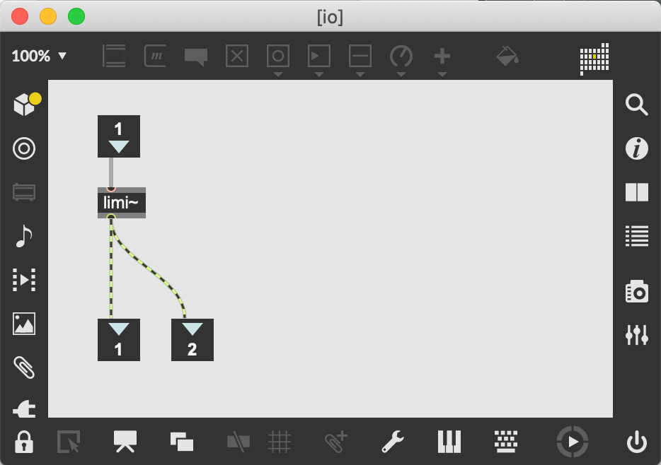
One last, little change: I created a simple subpatcher, which I called "io", that is going to be the last stage before output. I use it to split the single signal into two channels' worth of data, but I also slipped in a limi~ object in there as a way to prevent a complete explosion.

For the moment, I'm using whatever the default values there are for the object, but we'll probably beef this up in a future article.
In Review
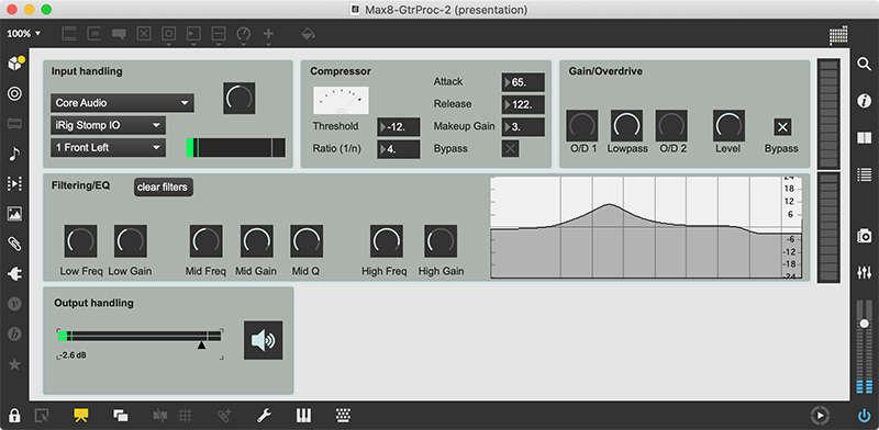
Put the patch into Presentation Mode, and you will see that I’ve reordered the modules to maintain the row-column orientation of the signal flow. I’ve also added level meters at the end of each row. This is something that I’ve learned to do for performance patches - to place meters in strategic places, helping me to see “where” something is wrong when something goes wrong. As this patch develops, we will place a meter at the end of each row, combining useful debugging information with a cool, flashy display.

I also decided to make the visual EQ/Filter display very large in Performance Mode. This helps me see the result of subtle changes and gives a better visual indication in the heat of battle. If you want to create and add modules of your own, you might want to make this part of the patch a little smaller — but be careful, since the EQ module can have a pretty drastic effect on your sound and you will want as much control as possible. With the addition of the overdrive and EQ/Filter units, we have created tools to sculpt the sound of the guitar. Next, we will add a few more “effect-y” modules, including a smooth phaser and a modulating delay line. Until then, have fun with our new modules, and try to make some of your own using some of the techniques we’ve developed.
Learn More: See all the articles in this series
by Darwin Grosse on 2021年5月25日

