
Help spectral delay theory

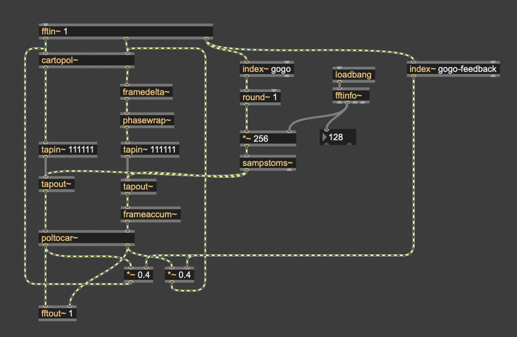
hi, I'm working on a spectral delay and I don't understand why we need these objects there: can somebody explain what happens with the imaginary values? I don't understand framedelta, phasewrap and frameaccum. What happens there and why?
Also what's the difference between using a feedback directly from tapout into tapin and the way it's setup now from poltocar to cartopol?

Let's say your FFT has 128 frequency bins. Then each sample in sequence in these audio cables represents one bin: bin 0, bin1, bin2, etc. up to bin 127, and then back to bin 0 again, every 128 samples. That's what the 3rd outlet of fftin~ is telling you -- the bin number.
(If you look at a spectroscope, bin0 is the left most column, bin1 is the next one to the right, and so on up to bin127 at the rightmost column.)
OK so most MSP~ signal processing objects that deal with time are going to have to take into account the fact that they are operating on one bin at a time. That's no problem for objects like +~ and *~ etc, because they just read their input samples and output the new value immediately, they have no "history" as such. But any operations that act on previous values will need to not simply read the previous sample (because the previous sample refers to a different frequency bin), but rather, read values from 128 samples ago, so that it is working with same frequency bin. So, for example, if you wanted to compare the difference in value of bin6 with the' previous value of bin6, then you actually need to compare it with the value 128 samples ago. That's what framedelta~ does for you.
Similarly, frameaccum~ is going to add up values over time for each bin, which means you need 128 separate values to keep track of, and you're adding to the last input 128 samples ago. That's what frameaccum~ does for you.
The patch above also applies delays, and again, because this is working with previous values, we want to make sure that the bins always match. For bin6 to read a previous value of bin6, we need to read 128, 256, 512, or some other multiple of 128 samples ago. Otherwise we'd end up moving data from one bin to another (which can be interesting sonically, but is not what this patch is intending to do.) That's why the patch uses a round~ operator, multiplied by the frame size, to specify the delay time -- it's always a whole number multiple of 128.
--
OK, the next part -- real & imaginary. This is a huge topic, but here's a minimal overview. Consider a sine oscillator as a point rotating in space (tracing out a circle). Like the moon orbiting the Earth. We can plot the X and Y coordinates over time -- one of them gives us a sine wave, the other gives us a cosine wave. OK if the input is a sine tuned to match a particular frequency bin of the FFT, then the "real" and "imaginary" outputs are really just the X and Y coordinates of this oscillation. A sine and a cosine.
One reason why having the X and Y coordinates ("cartesian" coordinates) like this is that you can then convert them to polar coordinates, using cartopol~. That gives you the distance and the angle to the rotating point. The distance is super useful, because this actually tells you about the amplitude or energy of the signal (for that frequency bin). For a standard sine wave, this value is going to be the same all the time, not wobbling up & down like the X or Y signals do. So it's an instantaneous measure that relates to "loudness".
The angle meanwhile tells you about phase -- at what angle the point is at in the central moment of the FFT. Phase here is measured in radians, which are angles that go from -pi to +pi, rather than from -180 to +180 degrees. It's important that the phases stay fairly continuous to avoid clicks or watery artefacts in the output. Often what we want to do is know how much the phase has changed between one FFT frame and the next (which we get from framedelta~), and we want to accumulate those changes over time so that they stay continuous (which we do with frameaccum~). Also we want to make sure that they stay within the -pi to +pi range (which is what phasewrap~ does for us).
Once we're done with our changes to distance & angle, we need to convert them back to X and Y ("real" and "imaginary") to send to the fftout~.
Hope this helps.

Thank you, LAURIN BAUMANN, for raising these questions I also had but didn’t dare to ask.
Thank you GRAHAM WAKEFIELD, for the clear and thorough responses.
A couple of additional questions, if I may, and my apologies if they sound too naive :
Why does the "history" mechanism you describe apply to the phase only, and not to the frequency ?
Why are there instances where this mechanism is not applied, like in the Forbidden Planet, for instance ? Shouldn't it be required all the time ? Besides, in the Forbidden Planet example, why the cartopol/poltocar objects are not needed ?

for a frequency filter (forbidden planet) you do not need polar, but you could also use it.
what does such a frequency filter do? as soon you change the amplitude, it changes the phases, too. (it is a general misunderstandment that a simple STFT frequency filter would give you a flat spectrum respose only because you eventualy removed the negative frequencies... it does not.)
now, for many processes you want to change phases and amplitudes separately, for example to preserve one of them, so you need polar conversion there.
simple example: a phase rotator - you do not want to chance the amplitudes (== frequency spectrum) here.
i totally understand the question in regards of the spectral delay, though. :)

Graham wrote:
what we want to do is know how much the phase has changed between one FFT frame and the next
Sébastien asked:
Why does the "history" mechanism you describe apply to the phase only, and not to the frequency ?
from here:
"The instantaneous frequency IS the temporal rate of change of the instantaneous phase."
some explanation here, too:
and here, too:
and related discussion here, too:
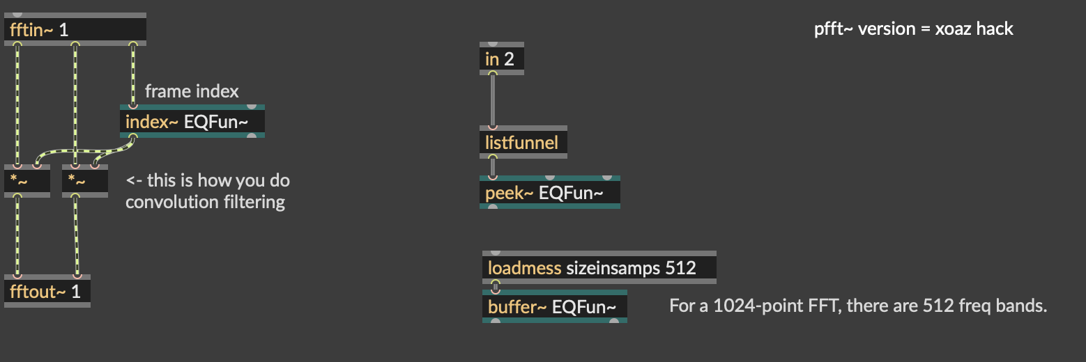
Why are there instances where this mechanism is not applied, like in the Forbidden Planet, for instance ?
The question is why does that patch not have to use cartopol / poltocar, right?
In that patch, both outputs of the fftin~ are scaled by the same amount. These are the "real" and "imaginary" outputs of a complex signal, but again, it is easier to think of these as X and Y coordinates of a point rotating around the centre. If you multiply the X and Y coordinates by the same number, the distance of the point from the centre changes, but the angle remains the same. If the angle remains the same, there is no change in phase. If the distance changes, there is a change in amplitude.
That patch is just changing amplitudes, so there's no necessity to work with polar coordinates.