A Basic Vocoder Tutorial, Part 2
Vocoders can be an insane amount of fun.
In part 1 of this series, we created a real-time analyzer (RTA). We did this using MC — the multi-channel/multi-band/multi-voice patching paradigm introduced in Max 8. In this installment, we will use the real-time analyzer patch we created as the starting point for creating a vocoder effect.
Where We've Been: The Real-Time Analyzer
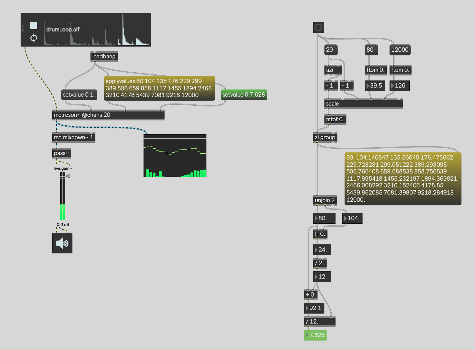
Here is the real-time analyzer patcher we created in Part 1 of this tutorial:

Remember that our RTA is taking a channel of audio and splitting it into a number of bands based on frequency. This functionality is similar to an equalizer, except that we are just splitting the bands up to do metering as a visualization – we aren't actually altering the content of each band.
The patching on the right-hand side of the patch calculates the frequencies for the bandpass filters (shown in yellow) and the ideal Q-factor (shown in green). We then take these values and include the bandpass filter frequencies and the Q factor in the patcher on the left as messages sent to the mc.reson~ object.
You can think of the mc.reson~ object as 20 traditional reson~ objects. In fact, it actually is 20 traditional reson~ objects — mc.reson~ is just a super-convenient wrapper for 20 reson~ objects.
What makes it a real-time analyzer is the live.meter~ object connected to the output of mc.reson~.
Introducing the mc.bands~ Abstraction
As it turns out, beginning with Max 8.1, Max ships with an abstraction that does all of the calculations we covered in the first part of our Vocoder tutorial — it is called mc.bands~. If you would like to see the mc.bands~ abstraction in action, check out the MC tab of the limi~ help files. It contains a patch that demonstrates how to use MC to create a multi-band limiter.
If we use mc.bands~ in our real-time analyzer, the resulting patcher looks like this.

The Vocoder
A vocoder works by taking the envelope (which is the volume level, roughly speaking) of each band of audio in one input signal called the exciter, and applying those volume levels to the corresponding bands of audio in another input signal called the carrier.
The classic example of this is using a voice as the exciter and a synthesizer as the carrier. The volume levels of the voice "excite" the same bands of audio in the carrier sound, which is a synthesizer. The result is that it sounds like the synthesizer is being played by the voice.
This is the reason we will need two copies of the mc.bands~ abstraction — we need one mc.bands~ abstraction to track the envelopes of the bands of audio in the exciter, and a second mc.bands~ abstraction for the carrier sound to which those envelopes will be applied.
Two Sources...
The patcher below establishes the excitation source (the drum loop) and the carrier source (a synthesizer with fixed frequencies).

The synthesizer, in this case, is a quick and dirty "supersaw" sawtooth wave playing the note A. It does this using MC with the use of the mc.saw~ object. That object is a wrapper around 12 copies of the traditional saw~ object. Each instance has a different frequency: either A (55 hz or a multiple of 55 hz) or a slightly detuned version of A that is "off" by 1 or 2 hertz.
Both the synth (the carrier) and the drumloop (the exciter) are passed through their own copies of the mc.bands~ abstraction to split the audio up into frequency regions.
To get the vocoder effect, we now need to combine them back together.
Making the Magic Happen

We have a number of options available to us to get the envelope of the bands of the drumloop (the exciter). One simple approach is to square the signal and then smooth the result. One side effect of squaring the signal (multiplying it by itself) is that all of the resultant samples will be positive —there will be no negative numbers.
We then need to smooth the signal out, for which a filter like the MSP slide~ object is appropriate. As we've done throughout this tutorial, we will use mc.slide~ to wrap 20 slide~ objects. One for each band.
Each band of the carrier (the synth) then has its gain controlled by the envelope (the output of the mc.slide~ object) of the matching band in the exciter. We mix the bands back into a single channel, et voilà!
Because there can be some loss in this process, I like to put a limiter with a gain boost at the end to ensure the result is audible. The MSP limi~ object is the perfect fit for this task.
What's Next?
We do, in fact, now have an actual vocoder!
Things to try include experimenting with different excitation sources and different carrier sources. A lot of great vocoders in the world also tie the carrier to the exciter. For example, the carrier can morph between pure tones and noise depending upon what the exciter is doing.
In the next part of this series we will turn our modest mono vocoder into a stereo vocoder. We will also investigate how we might begin to parameterize the vocoder.
If you come up with something fun, please share your variation in the comments!
Learn More: See all the articles in this series
by Timothy Place on September 1, 2020

