Making Connections: Connecting a Joystick to MaxMSP/Jitter
Max is all about making connections. The Making Connections series of tutorials will introduce you to new connections you can make between MaxMSP and the outside world. This tutorial, the first in the series, will discuss the use of HID devices such as USB game controllers as gestural interfaces for your Max patches.
Intro
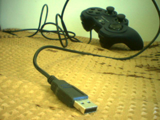
Since MaxMSP 4.5, the hi object has been included in the standard set of Max objects. This object allows you to get access to the stream of data coming from HID devices like USB joysticks. Using this object, we're going to look at using these extremely low-cost devices to provide gestural control of a Max patch. Once we have introduced the basics of making that connection, we'll also look into making some minor alterations to the hardware of your joystick for a more expanded use.
To follow along with this tutorial, you will want to find a USB game controller with a couple of analog controls. These are usually pretty inexpensive (less than $20 US) and can be found at any computer store. I personally prefer the ones with two small analog joysticks for your thumbs.
Download the Max 4.6 legacy patches and the updated Max 5 patches used in the tutorial.
HID in a Nutshell:
Before you dig out your Joystick, let's have a look at what HID is. The Human Interface Device(HID) class is a subset of the USB protocol specifically geared toward gadgets that provide some sort of interaction between humans and computers. The most common of these devices are keyboards, mice, and of course gaming controllers. When you plug a compliant device into your USB port, it will send a bunch of information to the OS about itself, like how many buttons or knobs it has and what range of data to expect. Because HID products can describe themselves to the OS so well, there is no need for manufacturers to cobble together device drivers and we don't need to search all over the internet to find them. Everybody is happy, except for the poor guy who has to write those HID Descriptors.
Making the Connection:
Ok, so now would be a good time to plug that Joystick into your computer. Once you've got your device plugged in, go ahead and start up MaxMSP and open the first included patch, 1.SimpleHInput. This patch demonstrates the most simple way to get HID data into Max.
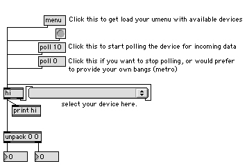
The first thing you will want to do is click the "menu" message. This will fill your umenu with a list of available HID devices attached to your computer. If you are on a Mac, don't be surprised to see your keyboard and mouse listed here (sorry, Windows users, the OS keeps those things to itself). Since we are most interested in the Joystick, select it from the umenu to tell hi to focus on it. If you start moving the analog sticks and pushing buttons, nothing happens, right? This is because we need to tell hi to start polling the device. There are two ways to do this. The first way is to send it a "poll n" message, giving it an interval in milliseconds. This uses an internal timing provided by the object. The other way would be to leave polling turned off and supply a source of bangs such as a metro. Once we get this running, you should see a stream of numbers in the two number boxes below as you press and move the controls on your device.
Managing the Data:
So now that you've got the object spitting out pairs of numbers, you'll probably need to harness those numbers in a way that makes some sense. Luckily, there is some logic to the way that HID reports are sent to your machine. For each control on the device, there is an index number. This is the first number in the list that comes out of hi. The second number that comes out is the value of that control. For example, an analog joystick will usually have two index numbers associated with it (x and y), and a value range of around 0-255 for each (more if you are lucky enough to have a 10-bit precision device).
With the knowledge that we are looking at pairs of numbers with the format {index value}, we can find a way to divide up this data in a sensible way. By using a route object after the hi, we can send each controller index to a different outlet. Because route strips the first element (index) of the list, each output will be the value of the associated control.
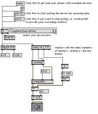
Using this information, we can create a simple control input for our patch, as shown in the next patch, 2.MakingSound. In order to make this patch work, you will first need to figure out the index numbers of a couple of controls. Try moving one of the analog sticks of your device. You will probably see two different index numbers coming out. Use these numbers to route the analog-x and analog-y signals to our sound-making subpatch. If the numbers are changing too quickly, have a look in the Max window at the printed data stream.
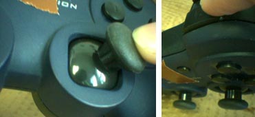
Now we will need to choose a button to use as our sound trigger. Pick whichever button you like and press it a few times. This will give you the index (remember that is the first number) of your button. Once you have changed the numbers in route and turned on the DSP, you should hear some sound when you hold down your trigger button. Now try moving the analog stick while holding it down...
In this patch, I am doing two things that are going to be vital whenever dealing with analog data - scaling and smoothing the data stream. If you look inside the p scaling subpatch, you will see that we are using zmap to scale the data to a usable range. The data is then converted to a signal using sig~ and smoothed using slide~. This prevents sudden transitions in the audio, which can cause clicks and pops in the output. The output of this patch is then sent to the simpleFM subpatch, which should be familiar to everyone who has used MSP.
Now that you have learned how to assign individual controls from your joystick, you can connect these values to control virtually any parameter in MaxMSP or Jitter. Try creating filter sweeps using the lores~ object or changing the delay and feedback of a tapin~ tapout~ network using your analog joystick. If you are using Jitter, you can assign the the analog stick values to a jit.xfade or other compositing object to create a video mixing system complete with clip triggering and control over different video parameters. With a little scaling or remapping of the values, you can create some very interesting controls for your patch.
A Deeper Connection:
Disclaimer: This section of the tutorial assumes basic familiarity with electronics and the use of soldering/desoldering tools. Cycling '74 assumes no responsiblity for damages to your gaming controller or any other device in following this tutorial.
Once you get the hang of it, connecting a joystick to control your patch will seem like no sweat at all, and you might start looking for another challenge. In this next section we will look at pulling the lid off of one of these devices and making a couple of simple alterations. The simplicity of a joystick's electronics make it a very affordable interface for connecting a few switches and knobs.
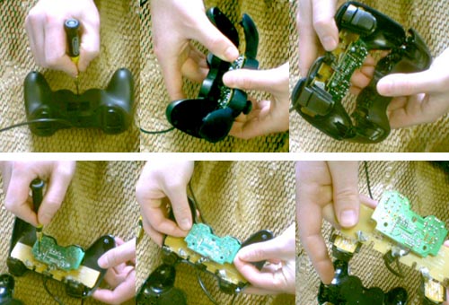
The first step to altering a joystick is to get the darn thing open. Most joysticks are simply screwed together on the back, so all you need to do is hunt down all the screws and unscrew them. There is usually one or two hiding under a sticker, so you'll want to check there as well.
The easiest thing to connect to your joystick circuit will be a switch of any sort. There are two ways you can accomplish this. The first way would be to solder the lead of your switch directly to the button contacts on the circuit board.
To demonstrate, we will solder in a mini toggle switch to replace one of the buttons of the joystick. To do this, we first attach a pair of wire leads to the switch. We then solder each wire from the switch to one half of the button contacts on the circuit board. Sometimes using a fine-grit sandpaper to clean the surface of the contacts will help the solder to bond better. Once you have soldered both leads in place, you will now have a classy switch to turn your patch off!
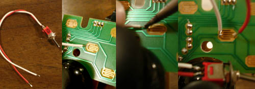
Depending on the joystick, this might be difficult to do, so often it is a bit cleaner to follow the traces on the circuit back to the little solder points that connect the traces to the chip. Soldering your leads to these points will usually be your best bet for the integrity of connection.
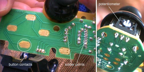
Switches are fun and very useful, but the analog controls are where a lot of the fun lies. If you look at the analog joystick elements, you may notice that each analog stick is really just two linear potentiometers connected to the circuit board. This means that any resistive sensor that has an appropriate range could easily take their place. However, before you can start connecting your flex sensors, you will need to first remove the joystick elements from the board. To do this, you will need a soldering iron and a desoldering tool (I personally prefer the bulb-type ones) to remove the solder that connects the joystick pots to the circuit. You will need to thoroughly desolder all of these points so that the joystick element will come off without too much trouble.
Once you've removed the joystick element, you can connect any variable resistance component in its place (e.g. photoresistor or flex sensor). Simply connect it the same way that the potentiometer was set up. For sensors that only have two leads, you will want to create a voltage divider by running a resistor between the sensor output and ground. You will probably want components that match the range of the joystick pots in resistance(~0-100k). Once you have connected the sensor you will be using, go ahead and start up MaxMSP and start playing.
Okay, so maybe it's not the easiest thing you've ever done, but it certainly beats designing a hardware controller from scratch. Which brings us to our final section...
Other Connections
Now that you know how to connect a USB joystick to MaxMSP, you might start hunting around for other devices that use the HID protocol. For all you brave DIY types, I recommend having a look at these projects that implement HID using commonly used microcontrollers:
Dan Overholt's CREATE USB Interface (PIC)
Mark T. Marshall's AVR-HID (AVR)
If you are interested in learning more about the HID protocol, check out the HID page at USB.org.
You can also take full advantage of the fascinating work being done by the gaming industry to provide more interesting controllers such as the floor-pads used for dancing games. All you need is the proper adaptors and a little knowledge and you can make the connection.
by Andrew Benson on March 12, 2007

