
Working with Hardware: Livid’s Code
The Livid Code is designed to be useable out of the box without programming. The default behavior of the Code's 32 encoders is to send values in the range of 0 to 127 as MIDI continuous controller (CC) messages. These messages can be easily assigned to software synthesizers to control parameters, providing a physical knob to any virtual instrument that supports controller mapping. The firmware of the Code produces an indication of the value on the LED ring that encircles each encoder.
This behavior, while handy, doesn't leverage the endless resolution of rotary encoders. The same thing could be accomplished with normal potentiometers without LED rings. If you want to unlock the true potential of the Code, you need to decouple the LED rings from the encoders. This tutorial will show you how to do this in Max, without resorting to JavaScript. Effectively, we'll get Max's interface to the Code down to a simple number box, and if you can manipulate a number box in Max, you can do some amazing things with the Code.
1 - initialize the code
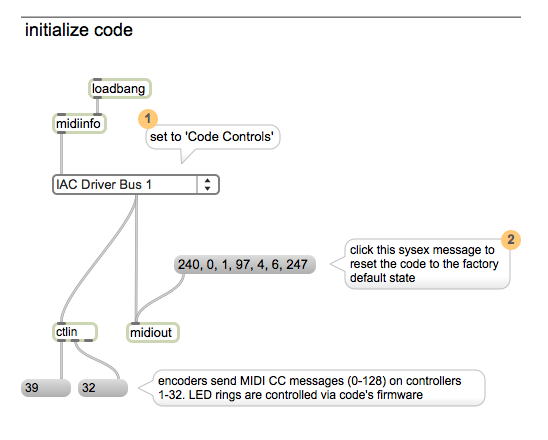
The first thing we need to do is set the Code to a known state. The best way to do that is to reset it to its factory default settings. All communication with the Code is accomplished via MIDI messages. The knobs and buttons on the Code send MIDI continuous controller or note messages. Messages that change change the behavior of the Code need to be a bit more flexible, so this is accomplished with system exclusive messages. The admittedly awesome Livid Code wiki details all the messages the Code responds to. Included in this tutorial are examples of these messages, formatted as working Max patches that you can easily adapt to your own use.
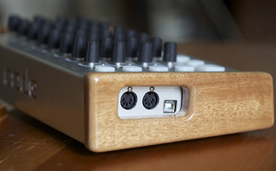
Even though the Code uses MIDI to communicate, you don't need to hook up the MIDI ports on the unit itself. All you need to connect is a single USB cable which both provides power and transports the data. No drivers are required to install.
The first patch example establishes the MIDI port on which the Code communicates. Click on the sysex string to reset the code. The ctlin object instantly responds to the values sent from the Code's encoders.
2 - decouple the LED rings
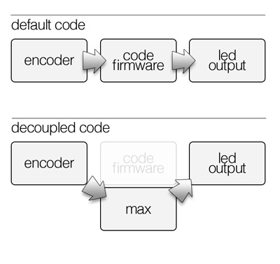
Now that the Code is in a known state, let's decouple the LED rings from the encoders. Currently, the internal firmware of the Code is controlling the LEDs, but we want to do this from Max. This is like turning local control off on a MIDI synthesizer, which decouples the sound engine from the keyboard, so the routing can be controlled with a computer.
Click on the sysex message in patch example 2 to tell the Code you want to change its behavior. Don't worry, you can always revert to the factory defaults with one click. Once you've done that, you'll notice the LEDs do not respond when you turn an encoder. This is what we want. Values are still sent out from the encoders, but if the LEDs are going to do anything, we're going to have to explicitly tell them to do so from Max.
3 - delta mode
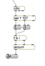
128 steps of resolution is suitable for a lot of tasks, but with rotary encoders, we have the ability to precisely tailor the value range. We want the encoders to tell us when they are incremented or decremented. Another sysex message puts the Code into 'delta mode' Now the Code sends a '1' on increment and a '127' on decrement. This may seem like a step backwards, but now the encoders are unbounded. In other words, they don't stop sending values when they reach 0 or 127. We can keep them unbounded or set the bounds ourselves to whatever we want.
We've built our own accumulator using the accum object to keep track of the increments and decrements as a running value. This produces an unbounded number that is edited with the first encoder on the Code.
4 - LED ring
Now let's put the LEDs under the control of Max. The state of each encoder ring is set with a two byte message. The first byte sets the left half of the LED ring, the second sets the right half.
Open the individual_LEDs subpatcher. You'll see a series of check boxes that correspond to each LED on encoder 1. Each LED is a bit representing its on/off state. The cumulative state of the left seven LEDs are packed together to fit inside a single byte. The same thing happens on the right side, albeit, the center LED is already represented in the first byte. Thus, any combination of the 13 LEDs can be represented with two numbers between 0 to 127. The frombin subpatcher formats the bits into the appropriate number.
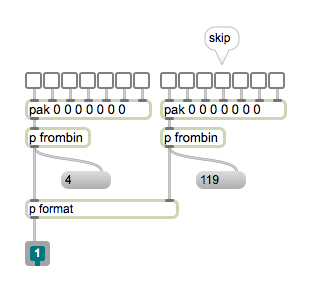
Back to the main patch, I've sequenced useful combinations of LED states into reusable primitives, like 'level' (rising cumulative clockwise values), 'indicator' ('interpolated' neighboring LEDs for more display resolution, like the default firmware mode) and pan (for bi-polar values). The coll objects contain two numbers (representing the two sides of the LED ring) and associates them to a simple index. This allows you to forget all this bit byte stuff and easily change the LED behavior of an encoder ring by using the data in one of these coll objects. You can easily create your own behaviors by designing patterns using the individual_LEDs subpatcher.
The format subpatcher takes the resulting two bytes and formats the rest of the sysex message to update the LED ring. Inside the subpatcher, you'll notice a pak with 64 inputs. There are 32 encoders, each with two 'sides'. The entire resulting sysex message encompasses all 32 encoders, so if you want to update the state of one encoder, you have to update all 32 of them. The upside is this is fairly efficient and the entire surface of the code (416 LEDs) can be safely/smoothly updated every 2ms or so.The pak object is good if the LEDs are directly driven from the encoder input, but if something else is driving the LED refresh, it is better to use a pack (or a join with one trigger input) and poll the first input at a regular rate.
5 - making the connection
Now let's connect the output of the encoder to the LEDs. Under 'initialize code' we have the full initialization sequence that resets the code, decouples the LEDs and sets the encoders to delta mode.
The accumulator last seen in patch 3 is now encapsulated in a subpatcher called 'accumulator'. We've arbitrarily decided on a bounded bi-polar resolution of 301 steps from -150 to 150. Additionally, we've pattr-enabled the accum object itself so we can remember and recall its value.
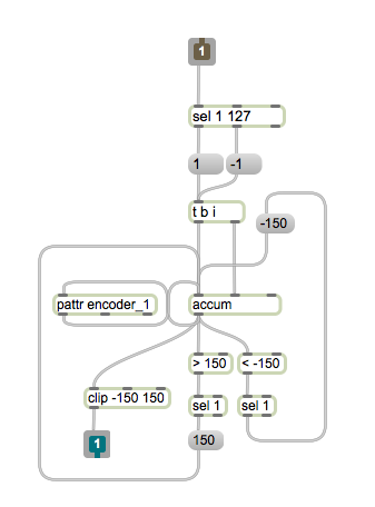
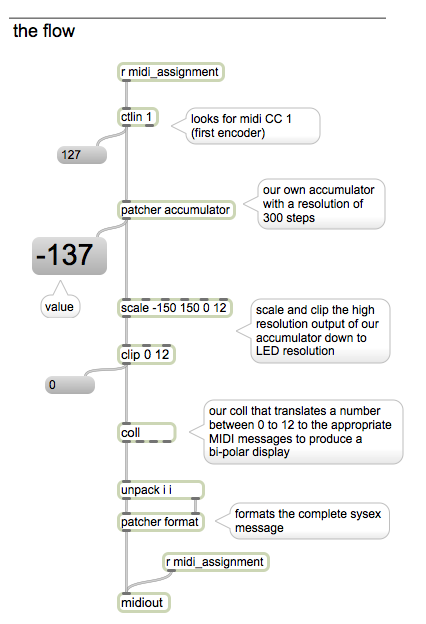
The output of the accumulator can be seen in the large message display labeled 'value' in the patch. We don't have 301 LEDs, so we need to scale this value down to our 13 LEDs per encoder. This gets sent into the pan-behavior coll seen in patcher 4 to represent a bi-polar value.
The pattr preset section demonstrates the value of placing the LEDs under software control. We can recall presets and even interpolate between them.
6 - example
The example patch takes everything we've learned in the previous patches and applies it to the entire code surface. This patch assembles three different encoder behaviors (volume, pan and indicator) into a typical mixer-type arrangement of eight 'channels' of four attributes.
The 'code ring' subpatcher formats the entire LED surface of the code into a single sysex message. The behavior and resolution of each individual encoder is assembled from some easily-modified, pre-built abstractions. The argument on each abstraction serves as an address for each encoder.
This demonstrates complete software control over the Code with Max and allows you to easily build code surfaces with different encoder resolutions, bounds and LED behaviors.
Application Examples
A synthesizer, or any music-technology product for that matter, can't be all things to all people. Max allows the creation of useful tools that are extremely specialized. It is fun to look at a control surface like the Code and design a music application from the interface down. When I looked at the 32 encoders of the Code, I immediately thought of additive synthesis. Additive offers distinctively beautiful clear tones, but is often ignored because programming partials is kind of dull. The Code offers some potentially fun and powerful ways to apply tactile surface to additive.
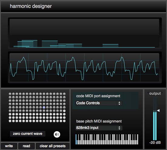
Harmonic Designer
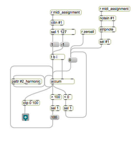
Harmonic Designer, included in the applications folder of this tutorial download package, is a 32-harmonic additive waveform designer. Harmonic Designer is a companion application for Wavestep and Drone Designer. Harrmonic Designer builds the wavetables that these applications use. The amplitude of each harmonic, starting with the fundamental and moving up the harmonic series, is programmed with the 32 encoders of the code. Press an encoder knob to zero the amplitude of that harmonic. Zero all the amplitudes, with the 'zero all' button. Waveforms are stored into slots of the preset object with a shift click. Collections of waveform presets are written to a json file (harmonics.json) which is read as a wavetable by the Wavestep and Drone Designer applications. Write the harmonics.json file into the wavestep and/or drone designer folders. The next time they launch, they'll use the new waves.
An accumulator abstraction, "ind", takes two arguments.
The Code's four rows of eight encoders output continuous controllers sequentially from 1 to 32. However, the humber follows a top to bottom order. In other words, the top left encoder is 1, the next encoder DOWN is 2. I tend to think of a string of 32 harmonics as progressing horizontally, so the accumulator abstraction for harmonic designer, "ind.maxpat" takes two arguments. The first argument specifies which hardware encoder (1-32). The second argument specifies the data order. So, the argument of 'ind 5 2' specifies the next encoder to to the RIGHT of the first encoder (5) is the (2) second harmonic.
Drone Designer
Drone Designer is a four-voice wave interpolation synthesizer built specifically for drones. Drone Designer plays back waves created with Harmonic Designer. Two waves are specified as an 'A' wave and a 'B' wave. Interpolating between these waves creates smooth timbral shifts. The resulting continuously morphing wave is then sent to a tremolo effect. Exploring the interplay of these two modulations is where the fun is at. Then you can start layering voices.
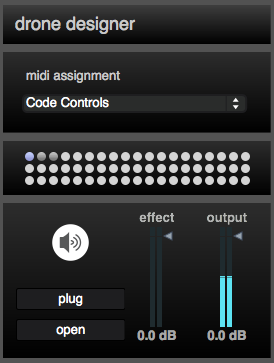
Each voice has eight parameters. Each row of encoders on the Code represents one 'voice'. Drone Designer plays back the waves created in Harmonic Designer.
column one: tremolo rate
column two: wave interpolation rate
column three: pitch
column four: wave a
column five: wave b
column six: volume
column seven: pan
column eight: effects send
The four row buttons mute/unmute individual voices.
All the encoders in Harmonic Designer behave the same way. So, they all share the same encoder abstraction. Drone Designer uses encoders of varying resolution, so each class of encoder behavior shares its own, unique abstraction. For example, the pitch encoder has a range from 12 to 80 but the LFO rate encoders use a range from 0-150.
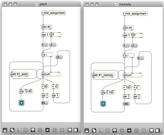
The two wave encoders differ subtly as they each access a different wave location. Otherwise, they're identical.
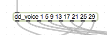
The dd_voice abstraction collects the encoder inputs for each voice and produces the sound.
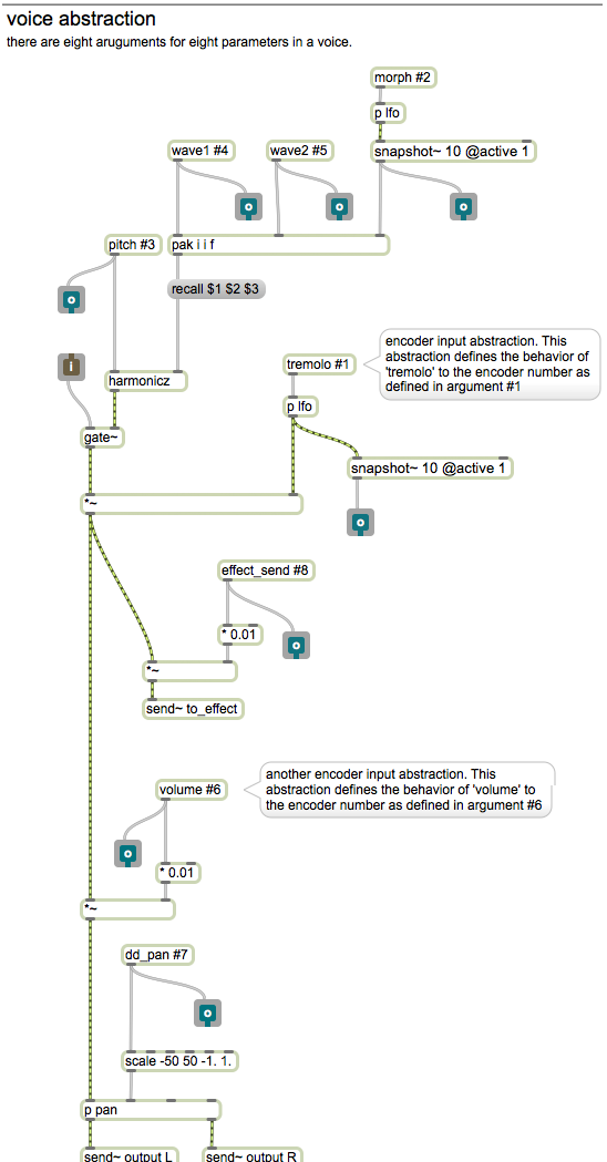
There are eight parameters within dd_voice. The eight arguments on designate which encoders are used. For example, the argument: 1 5 9 13 17 21 25 29 specifies the top row of encoders on the Code.
The LEDs still have to be rendered so the outlets of dd_voice feed the code_ring subpatcher that formats the huge sysex message that updates every LED ring on the Code. The LFOs that govern the tremolo and wave morphing effect display the phase of the LFO output. so the entire LED surface of the code is updated every few milliseconds. This is a good example of a totally decoupled encoder/led action. A graphic representation of the LFO rate provides more feedback than an arbitrary indicator bar.
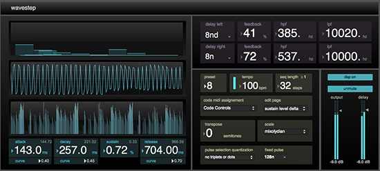
Wavestep
Wavestep is an additive synthesis sequencer instrument. The sequencer controls both pitch and relevant synthesis parameters, such as which wave used. There are 32 steps to program. The eight buttons across the bottom of the code select which parameter is edited. Each encoder on the code represents one of the 32 steps of parameters on that page.
Previous examples of uncoupled code operation involve formatting the data from the code's encoders into messages that control the behavior of the LED rings. Wavestep also formats the data into strings that write structured data into a dict object.
The sequence output is constructed from reading the structured data back from the file.
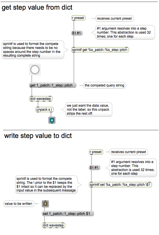
Describing all the dict bits is beyond the scope of this working with hardware tutorial, but if you're looking for an example of interfacing a control surface with dict, this application may offer some insight.
There is no edit buffer, so there is no need for a save button. Be aware that any editing you do is written immediately into the current preset. If you want to start from scratch, select an unused preset and start from there, or use the randomize preset.maxpat concurrently with wavestep after you have selected a preset. The randomizer will write directly into the current preset. If you wish to set every step to the same value, use a very small range on the range slider.
The order of the eight edit pages, as accessed on the Code are:
pitch (base pitch of step) (pressing encoder button enables/disables step)
wave (wave selection) (pressing encoder button enables/disables wave interpolation)
gate time delta (gate time is determined by the step duration parameter. this parameter modulates the gate time)
attack time delta (this parameter modules the attack time of the envelope)
decay time delta (this parameter modules the decay time of the envelope)
sustain time delta (this parameter modules the sustain level of the envelope)
release time delta (this parameter modules the release time of the envelope)
step duration (*determines the duration of the step in tempo relative units from 128n to 1nd)
* this parameter is ignored if pulse selection is set to fixed. In that case, the pulse is determined by the fixed pulse menu
That concludes the third and final part of our first Working With Hardware feature on the Livid Code. Although the examples are specific to the that surface, the techniques we explored can be applied to any hardware interface.
by Matthew Davidson on 2012年2月14日 17:24


