Create a Simple Arduino Connection
Examine the Connection
The Arduino microprocessor board is one of the most-used hardware devices in the Media Art world. There are many reasons for its popularity: it is relatively low-cost, has a multitude of hardware extensions (called shields) available, and has a simplified toolchain that runs with no operating system overhead.
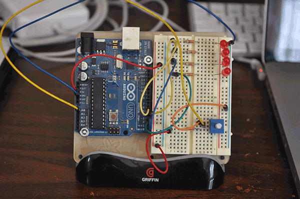
Using the Arduino with your Max programming is actually quite simple: you use a serial port connection to talk to a "sketch" (a small program) that runs on the Arduino itself. There are some existing Max projects that communicate with the Arduino - the Maxuino project is one of the most popular - but often people want to have a purpose-built program running on the Arduino, and higher-level functions running in Max. That's what this article series is going to explore: a very simple Arduino sketch, combined with a simple Max patch, both of which to combine to create a two-way communication between Arduino and laptop.
Let's start with creating the hardware circuit we will need for our example...
Step 1: Create an Arduino-based Circuit
We will begin our Arduino connection by creating a simple circuit. This circuit will use a small potentiometer for input, and four LEDs for visual output. The parts necessary for this circuit include:
An Arduino board (we will be using an Arduino Uno)
A small breadboard
A variety of jumper wires
Four (4) LEDs of any color
Five (5) 330 ohm resistors
One breadboard-mounting potentiometer
Using these parts, create the following circuit layout:
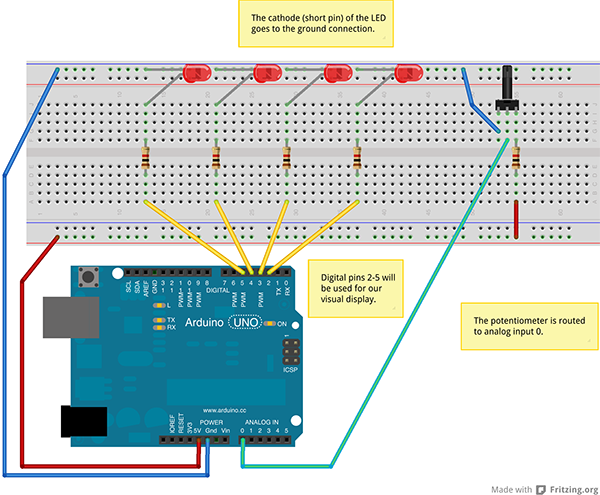
(You can download the Fritzing file here: SimpleArduinoConnection-02fzz.zip)
A few notes about this circuit:
You will be plugging the Arduino into the computer for serial communication with the computer (and Max). Most Arduino boards have a USB port that provides power to the device. We tap into that power for the simple circuit we've created.
We use digital pins 2 - 5 for our LED display. You generally don't want to use pins 0 and 1, since they are used for serial communication.
In order to prevent overtaxing the power supply of the Arduino, use use the 330 ohm resistors as "current limiting resistors" - they reduce the amount of current drawn from the Arduino board, and prevent the LEDs from burning out.
You can see a picture of my circuit board creation in the Introduction section.
Now that we have our circuit ready, let's create an Arduino sketch that tests our board, and prepares it for communication with Max.
Create the Arduino Sketch
Arduino programs are called sketches, and represent a Javascript-like language for developing on that platform. In order to make our Max-to-Arduino connection work, we need to make a new sketch, and load it onto the Arduino device. The sketch we will use is as follows:
//
// Simple Max-Connection Sketch
//
// by Darwin Grosse for Cycling '74
//
// Note: This sketch uses simple coding - rather than efficient coding. No attempt is made to be clever - rather,
// the goal is to make a sketch that will be easy for people to modify regardless of experience level.
//
// --------------------------------------------------------------------------------------------------------------
// variable setup
byte incoming; // this is where we will store incoming serial data
byte last_analog = -1; // we start with a negative number so that the first reading will give us a new value!
// the setup part of the sketch
void setup() {
// we need to set up the serial port for communication with the computer
Serial.begin(57600);
// we need to set up the four digital pins for output. We will also flash the lights to show we have
// a good program.
for (int i=2; i 0) { // if we have incoming data from the computer...
incoming = Serial.read(); // get one byte from the serial port
switch (incoming) {
case 0: // if the byte is 0
digitalWrite(2, LOW); // turn off pin 2
break;
case 1: // if the byte is 1
digitalWrite(2, HIGH); // turn on pin 2
break;
case 2: // if the byte is 2
digitalWrite(3, LOW); // turn off pin 3
break;
case 3: // if the byte is 3
digitalWrite(3, HIGH); // turn on pin 3
break;
case 4: // if the byte is 4
digitalWrite(4, LOW); // turn off pin 4
break;
case 5: // if the byte is 5
digitalWrite(4, HIGH); // turn on pin 4
break;
case 6: // if the byte is 6
digitalWrite(5, LOW); // turn off pin 5
break;
case 7: // if the byte is 7
digitalWrite(5, HIGH); // turn on pin 5
break;
}
} // end of if for Serial.available()
// This is where is check the current value of the potentiometer, and send the value if it has changed.
// ----------------------------------------------------------------------------------------------------
incoming = analogRead(0) >> 3; // get the current value of the control
// strip the 3 lowest bits - to prevent jitter, and to put the value
// in the typical MIDI range of 0 - 127
if (incoming != last_analog) { // make sure it has changed...
Serial.write(incoming); // send the byte to the computer
last_analog = incoming; // save the new data
} // end of if values have changed
} // end of loop()
You can download the sketch here: SimpleMaxSketch.ino.zip
A few things to notice. First, we are using the following data to turn on and off the LEDs:
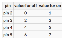
This is a pretty easy protocol to follow, and will be easy to implement in Max code. Conversely, in order to make the data coming into Max easy to use, we change the analog read value to be in the range of 0-127. This way, it "looks" like MIDI data, and will fit in easily within our patching environment.
In order to use the sketch, you will have to use the Arduino application to compile and load it onto your device. The code stays "on" the board until you load another sketch, so once it is in place, you can close down the Arduino software.
Now the Arduino is all set up, and it's time to dive into making a Max patch.
Create a Test Max Patch
NOTE: Before you start working on the Max patch, you have to exit out of the Arduino application. Since both the Arduino app and Max will try to control the serial port, they will be in contention if you try running both at the same time.
Now let's make a test program to verify that our sketch - and our hardware setup - are all working correctly. We'll do it step-by-step so that each part is clear.
First, we need to create a serial port connection to the Arduino, and build the surrounding application pieces necessary to select a port and to report information from the port:
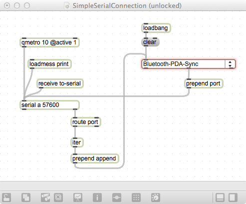
A few things to note here:
The setup of the menu (which contains all of the available serial ports) occurs when the patch is loaded (that's the loadmess object).
A qmetro is used to start firing off bang messages, which serve as a polling system for incoming serial bytes.
The {maxword|name=serial} object needs to be initialized with the same baud rate that we used in the sketch - 57600 in this case.
When working with the Arduino, you never know what the serial port name is going to be - or where it is going to show up in a list of ports. That's why you have to use a menu for port selection.
A special {maxword|name=receive} object (called to-serial) is created for us to use in the next step.
Next, we need to put in the pieces that send data to the Arduino and receive values back from the Arduino. Here are those additions, highlighted in red:
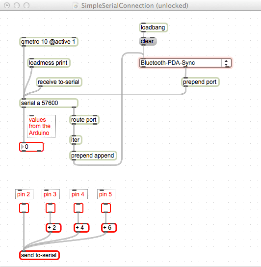
You can download this test file (sans the garish red outlines) from here: SimpleSerialConnection.maxpat
If the connection to the Arduino is set up correctly, and our connection sketch is loaded, you should be able to click on each of the "pin" checkboxes to turn the corresponding LEDs on and off. Also, if you turn the potentiometer wired into the Arduino, you should see the value (in a range from 0 to 127) appear in the number box below the {maxword|name=serial} object. We have communication!
Now, let's use this setup to create a simple "light sequencer" to show a more interesting use of this setup.
Creating a Useful (Sorta...) Patch
With a few additions to our test patch, we can actually make something that shows an interesting connection between Max and the Arduino. In this case, we will use the data from the potentiometer to set the speed of a clock, and generate random output to strobe the lights. Ultra-simple, but hopefully it provides you with the means to do something more valuable for yourself.
Here's the "Final" patch of this series. I've marked the new objects in different colors:
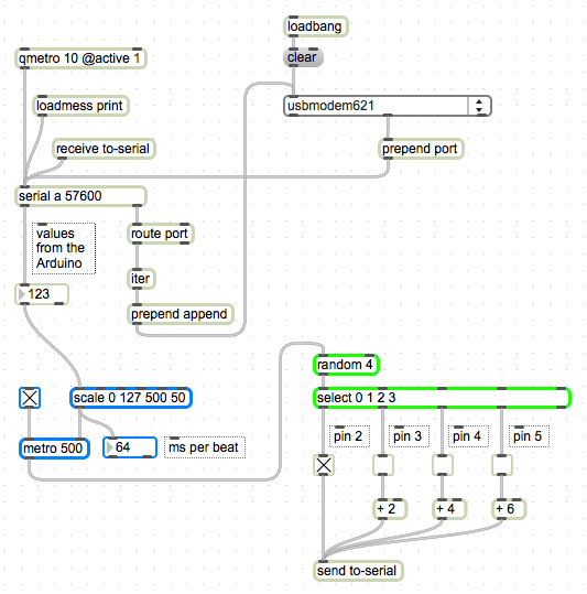
You can download this patch from here: SimpleSerialConnection-2.maxpat
The Clock
Let's first look at the blue objects. This section uses a metro object as a clock, a toggle as an on/off switch for the clock, and a scale object to handle the nasty math of the thing. The scale is most important: it takes the incoming range of values (0 through 127) and changes it to a descending - but larger - range of values (500 down to 50). We want to make it descending so that a smaller number creates a longer time between clock pulses.
If we select the proper serial port in the menu, we should be able to see the number box (labeled ms per beat) change within the range of our scale object. Depending on the size of the resistor that you have connected to the potentiometer, you may not be able to get the full range. For example, with a 330 ohm resistor, I was getting the range of 0-123 as input from the Arduino.
The Random Blinkie Lights
To get a set of blinkie lights going, we will look at the objects outlined in green. The first object is a random object with an argument of 4. Since the argument represents the range of values, and random values start with zero, it means that our output will be from 0 to 3. Next, we use a select object to determine which value (0, 1, 2 or 3) was output by random, and use that to switch the state of the toggle switches we created earlier.
If we connect the metro/clock to the random object, we will send digital pin controls that turn on and off randomly, and whose speed is controlled by the potentiometer.
Conclusion
Hopefully, this patch reveals how easy it is to connect your Arduino to a Max patch, and how two-way communication is an easy way to turn the focus from the computer screen to hardware. From here, you should be able to extend and enhance both the Arduino sketch as well as the Max patch to make something that is unique to your vision - and a whole lot more artistic than this!
by Darwin Grosse on May 3, 2013

