Noise Tutorial 1: Riding Tandem With The Random

In the last several tutorials I’ve written, I’ve been talking about a subject that interests me a great deal – how to add variety to a Max patch in ways that both provide you with surprising and interesting combinations and do so in ways that make the transition between your input and what your patch is doing more subtle than hitting a button object and having everything start behaving in ways that are obviously not you.
To be more specific, I’ve been talking about ways to use the humble LFO as a generator of that variety by summing, sampling, and otherwise using it to produce less ordinary control curves than can be easily intuited by your audience by the time the second sweep of the LFO comes around.
There’s another obvious source of variety generation that Max users often gravitate toward: random number generators. For many Max users, a random number object driven by a metro object whose output is connected to a makenote/noteout object pair is one of the first Max patches they see and hear.

This time out, I’m going to try to create some tutorials that work with the idea of randomness and noise as a starting point in the same way as I’ve created tutorials about using LFOs as generators of variety.
The problem with randomness
Okay – the header was supposed to be provocative to grab your attention. There’s nothing wrong with noise and randomness – noise occasionally sounds really interesting (especially its colored varieties, and it’s provided any number of interesting sources for interesting music.
For me, though, there’s a problem – I’m not random. I don't do a very reasonable imitation of randomness, and randomness sure doesn't imitate me very well. And, apart from situations in which I want to introduce very minor changes to delay times or pitch to create audio effects, it always tends to sound... well... random. When you throw the switch on your random generator, everyone in the audience who isn't completely tranquilized is going to know in N picoseconds flat that you've handed stuff off.
But as a source of possible materials to use, it's just fine. To put it another way, while noise may generates variety well, I don’t find that it organizes variety to my satisfaction. When I use it, I tend to take it as a starting point - it's an endless source of potential futures to mess around with. And that’s what this tutorial is about.
I’m going to show you some ways to think about using randomness as a starting point, and using some basic Max tools and techniques to coax that randomness into some interesting forms of control. I’m going to use Jitter to generate images and then distill them down to shiny sequences of data we can use to control things. The original idea came to me while watching someone else perform. While listening carefully, I thought I recognized some of the performer’s audio as the output of a Buddha Box. Sure enough, there it was hidden away on the table. All the person up on stage wanted was some interesting and easily controllable backgrounds, and I got to wondering how I could make a device that would not only do that, but allow me a little more freedom and a little less immediate recognizability.
Come on see the noise
The first and most obvious question you’ve got is probably to wonder why I’m interested in using Jitter to make noise. As I try patiently and often to explain to new Max users that while Jitter does an awesome job of processing images, it’s really about processing big blocks of data in a Max-like way and then converting the result so that it looks like a video image. Each and every pixel in a video is one cell of a matrix the size of the video image that has four “planes” - each of which contains a value that describes the RGB color value of that pixel along with an alpha channel value that’s useful for things like chromakeying. Although you’re seeing an image, you’re looking at numbers.
I’ll be using Jitter to generate the random numbers that are the basis for the device I’m building this tutorial around. The simple reason is that it’s a quick and easy way to generate a whole lot of random numbers, and that means we can use what you might normally think of as image processing objects in Jitter to massage data, as well.
So here’s the heart of our patch - the jit.noise object.

The jit.noise object generates “white noise” in the form of matrices of random values. In this case, the arguments to the jit.noise object (4 char 16 16)specify that we’re producing a matrix composed of 16 rows and 16 columns of noise - a total of 256 different char data values, each of which is an integer between 0 and 255. The first argument specifies that we’re producing a matrix with four separate planes of data - every time we hit the button, four new and different matrices full of random values will be produced. But keep in mind that while the graphic display of this matrix full of noise looks like a happy little multicolored mosaic, you’re really looking at data.
It’s just a bunch of numbers - in fact, we could just as easily be looking at other kinds of data - a sequence of the last 256 MIDI notes we played on our keyboard, a representation of satellite telemetry data from an unmanned drone cruising a distant border, or 64 of our friends’ favorite colors expressed as CMYK values. The only thing that matters is that we have four different sets of 256 random number values, each in the range 0 - 256. We can do anything we want to with that data. In this case, we’re going to grab slices of the data, convert the slices to lists, and then use some interesting Jitter objects to change the ways those lists look and behave.
Matrix carving (however you slice it)
It might have occurred to you as you looked at the jit.noise patch that you were really seeing rows and columns of data – 16 rows of lists of data 16 items long each way for each of the four planes of data in our noise matrix. Jitter gives us an object called jit.submatrix that we can use to carve arbitrary slices out of any matrix full of data and convert the data to plain old everyday Max data lists that we can use for whatever purposes we want. Here’s how it works:
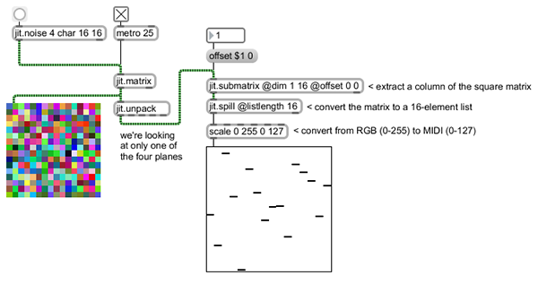
You’ll note that we’ve added some new objects to this patch
We’re using a jit.matrix object to store the noise matrix and a metro object to run our patch so we can extract data on the fly.
The jit.submatrix object lets us choose what part of the 16 x 16 matrix we want to look at (using the @dim (dimension) attribute), and the point at which we start our slice (using the @offset attribute). In this case, we’re creating a matrix that is 1 cell wide and 16 cells high (a column of data!) whose upper corner is located at the left and top corner (0 0). If we wanted to grab a horizontal slice of the larger matrix data, we would have typed jit.submatrix @dim 16 1 @offset 0 0 into the object box). We can choose column or row of data we want by sending the message offset n 0, where n is a number between 0 and 15 (i.e., the first or last column) and 15. To choose a row of data, we’d send the message offset O n to the jit.submatrix object we’re using to grab rows of data
The jit.spill object takes the resulting matrix and unrolls it into a plain old everyday Max list of a length we specify using the @listlength attribute.
Finally, the trusty scale object converts the items in the unrolled list from a data range of 0 – 256 to something I find a bit more useful – data in the MIDI data range of 0 – 127. The multislider object displays the resulting list of data and will display any of the columns we choose on the fly (Note: I’ve set minimum and maximum output values for the integer number box connected to the message box to only send numbers in the range 0 – 15).
We now have a way to grab rows or column from our noisy data set for each and every one of the four different data planes. That’s 8 different 16-element lists of MIDI-style control data. But we’re just getting started!
Image processing for MIDI users
Jitter comes with a number of different filters that produce interesting visual effects – if you use Jitter, I'm sure you may have a few favorites you use all the time. I’ll say this again: since Jitter is actually just manipulating numerical data for each element in a matrix that represents an image, we can use visual filters to process data. Jitter doesn't care what the matrix values represent or where the data comes from - if it's the right kind of data and planecount, a Jitter object will process the data and pass it along.
Here's an example of one of my favorite Jitter filters: jit.plur. This nifty filter performs linear interpolation on incoming matrix frames - it resamples the image, and then interpolates back to the original size.

We’re going to use that object to process our visual noise matrix.
Here's the original patch with a jit.plur object added (along with a little encapsulation to clean things up a bit). What's interesting here is to watch what happens to the row and column multislider objects as we change the x_step and y_step input values - the interpolation takes the random slider values and begins to create new, more "linear" data outputs with nothing more than a change in a number box.
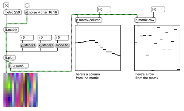
You'll note that there's an additional mode message that lets you choose from 15 different kinds of interpolation modes in addition to the standard linear mode (mode 0). The visual display will give you some idea of what happens on the image side, but it's obvious that not all of these modes produce useful output for our purposes - modes 5 through 9 look promising, modes 1, 3, 4, 11, and 13 tend to zero out the column values, and modes 2, 10, 14, and 15 are pretty much useless. But hey - that's 5 more interesting possibilities for performance!
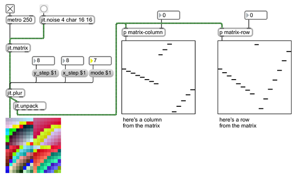
Now we've got a really interesting way to generate random data sets that we can use to create anything from completely random output to nice linear ramps. So far, I’ve only showed you the output of one of the four planes of the Jitter matrix (I did it to make the patches easier to follow). Actually, our patch is producing four times that amount of data, all ready for us to use - even the plane of my matrix that includes alpha-channel values (they're normally all set to 255 when we're displaying a normal image) is full of useful noise. And we can grab rows and columns for each of those data sets, too.
Scale mapping for fun and profit
No matter how nicely interpolated the data sets my noise matrix is kicking out may be, they're still producing output that says "random" in big 20-foot screaming' day-glow puce capital letters to my ears (I apologize to any 12-tone composers out there who may be offended): it's still based on 12 notes per scale. Although the scale/tuning I work with isn't the normal 12 tones of Equal Temperament and you might be fooled, I still prefer to select a subset of those twelve notes myself. So I'm going to add the ability to remap the output of my noise matrix.
As you may have noticed, almost any task has a wide variety of possible solutions in Max. The method I'm going to show you here isn't necessarily the best or the fastest or even the smartest. It's just how I do it, and it includes a few odd quirks that I've decided were features rather than mistakes.
You've got to start somewhere, so I'm doing mappings relative to a single scale in the range of middle C (MIDI notes 60 to 71). I'm also making use of the ability for number boxes in Max and Max for Live to display MIDI note numbers, since they're easier for me to work with.
Let's look inside the scale-designer subpatch.
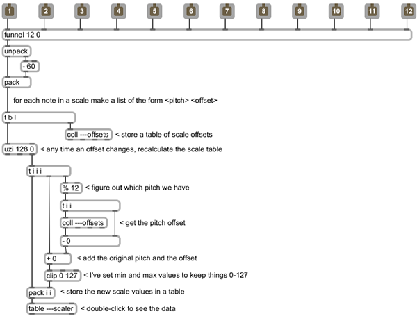
The heart of the patch is simple: each note in the scale has an offset associated with it that comes from comparing the note values I set in the user interface with the "normal" note. Each of those 12 note offset values are used to create a list that gets stored in a coll (a nice feature here is that I can use wide offset ranges or octaves rather than simply "transpose this value up 2 semitones....”). Whenever any of the twelve note values changes, I use the insanely useful trigger object to update the coll and then create a table containing all 128 notes in the MIDI range. In this patch, the output index from the uzi object is used as a counter to step through the MIDI range, applying the offset value for each note in the scale (using the remainder object with an argument of 12 will give us note values regardless of octave) to each and every incidence of that note) and then storing it in a table object. Note that we’re also using the clip object to make sure that the contents of the table remain in the range 0-127 as we apply the offsets.
You may also notice that the names of the coll and table objects in the example patch begin with three dashes (e.g., ---scaler). I'm doing that because I'd like to use this patch inside a Max for Live device. When you work with Max, the data space is global - any table object named kitchen can be accessed anywhere else in your max patch by adding a table object with the same name. But what if you create a Max for Live device and you want to use a copy of the same device on another track? If you named the table objects in the patcher scale-offsets, then every single one of the Max for Live devices you use would refer to the very same table. In some cases, that's really useful, but not here. By starting the name of the coll and table objects I'm using in this patch with three dashes, I'm creating different copies of the coll and table objects for each version of the Max for Live device I create, so that the device on Track 4 can have different tuning maps than the device on Track 5.
Here's what the resulting table looks like when I specify a scale mapping I commonly use for a 5-tone Javanese scale in the tuning I use:

Now that I've got my note mappings all set up, there's one more improvement I'd like to add - it'd be interesting to be able to take my interpolated noise and to map it to some range other than the full range of MIDI note numbers. There are several reasons I might want to do that - I can use that feature to shrink down the mapping range to fit something with a narrow range of MIDI notes such as a drum machine, or I might want to map each of the four separate noise plane outputs to different MIDI note ranges, or note ranges that overlap. Since I've got my scale-designer patch, any rescaling I do will always be mapped to MIDI notes I want, so I'll add a new patcher called range-mapper for the rows and columns that will let me choose a base note, and then scale the noise output across a range of possible output notes.
Here’s how the range-mapper patcher looks on the inside:

The reason I like using base and range scaling for outputs is simple: not only can I easily get nice octave divisions by specifying base values, but using the same base and different ranges easily produces outputs that are different but have some of the same features in terms of general contour (if you're curious about this, you might want to experiment with two outputs that share the same base but use 12 and 24 for their respective ranges).
Wrapping it up and making some noise
One way to think of the data display we have has probably occurred to you - it's an odd variety of a step sequencer whose steps are derived from noise rather than an input sequence of some kind. That works to my advantage - retrieving data from any of the displays is a simple matter of sending the message fetch [slider number]" to the multislider object, and retrieving the output data from the right outlet of the multislider object just as we would do with any step sequencer constructed using the multislider.
The arrival of varieties of Max objects that work with musical time and their support in Max for Live makes working with all this data even more of a pleasure - we simply use a set of locked metro objects and counter objects to create output on the fly. In the example device I'm building, I'm using the horizontal scans to generate note numbers and the vertical scans for velocity information. A few judiciously placed makenote objects (which use the same units of musical time to specify duration as the metro objects) and a noteout to ship the data to my downstream synth and things are ready to go.
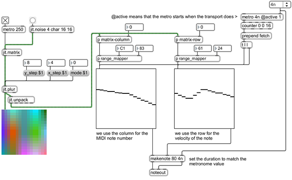
One other little “improvement” occurred to me while I was patching and listening to my device happily spitting out cyclically repeating patterns – a consequence of using base and range scale mapping is that certain kinds of contours create repeating notes when mapped to narrow output ranges. As I was sitting around patching and listening, it occurred to me that one way to add a little interest to the proceedings would be to filter out repeats of a note in a way that would create occasional silences. Of course, the change object is perfect for exactly that sort of task, so I added a simple little subpatch called play-handler that took the note number output and let me switch between repeating and nonrepeating patterns.

Creating the final Max for Live device involved taking the basic patches I’ve showed you, duplicating the relevant portions so that we can use all four planes worth of data, and spending a little time doing the necessary housekeeping to enable our device to save initial states, to make the parameters available for automation, and to enable the creation and saving of presets.
While this tutorial includes a finished device that’s had all the necessary work done, it’s still useful to remind you of the steps necessary to create your Max for Live device’s user interface and set it up to work with presets:
1. Go through the Max patch and make some basic decisions about what parts of the patch you want to see and what data parameters you’ll want to be able to set or modify. If you haven’t been using Max for Live-specific objects in the patch, to through the patch and replace all the standard Max user interface objects (such as number box objects) with their equivalent for Max for Live.
Note: while there is no live-specific version of the multislider object, we don’t need to worry about it – we’re using the objects to display matrix output rather than storing any initial states. Since I’m just using the object for display, I also checked the Ignore Click attribute in the multislider objects’ Inspectors
2. For each parameter you want to use, add a pattr object with an argument that specifies the parameter name as you wish to see it for automation (e.g. pattr channel1-enable). Connect the center outlet (the bindto outlet) of the pattr object to the inlet of the user interface object. Select the pattr object, open its Inspector, and click in the Parameter Mode Enable checkbox. The object to which the pattr object is connected will now have its Scripting Name, Long Name, and Short Name set to match the argument you gave the pattr object, and a group of new attributes will appear in the Inspector. Click in the Initial Enable checkbox, and enter an initial value for the user interface object.
3. Add a pattrstorage object to your patch, and name it using an argument (e.g. pattrstorage mydevice). Open the pattrstorage object’s Inspector and click in the Parameter Mode Enable checkbox. You’ll also find an attribute called savemode, which is set to 1 by default. That attribute value should be set to 0 so that you won’t be prompted to save changes to your presets.
One optional step you might consider if you’re thinking of sharing your device would be to select the Annotation for each object in your device and type in a description of what the interface object does. When you enter some text, a little ghostly square will appear on the object in the patcher window to let you know that you’ve entered text. That text will be displayed in Live’s Info panel when you place your cursor over the interface element

Once you’ve taken care of that housekeeping, you’ll have a device that loads and saves presets properly, and clear and readable labels you can see when working with automation. Beyond, that, you’ll have to make some decisions about how to display your other data.
In the case of my device, displaying all that visual data is an interesting challenge. After trying several possible solutions that didn’t work well for me, I decided to show each of the four data planes, and to show both the row and column data on the same display. To do this, I’ve set one of each of the multislider object pairs that represent a data plane with a dark background and the other with a transparent background and no border. When used in the Presentation mode, I can overlap the multislider objects to create a display that simultaneously shows both rows and columns for each of the four data planes. Of course, you may have other ideas.
Remember that in order to make use of this feature, you need to open the patcher Inspector from the View menu and click on the Open In Presentation checkbox.

Nothing to do now but play
So here’s an example Max for Live device to get you started thinking about other ways to use random data in your live performances. The careful reader will note that I’ve made no attempt to save any of the data – this is a device whose initial state really is random, although you’ve got a fairly good amount of control about how to shape its output. Drop the finished noizmatrix device onto a MIDI track and give it a whirl. Note that since it’s a MIDI Effects device, you’ll need to add a synth of your choice “downstream” of the device to produce audio output. I hope you find it inspiring and interesting.
by Gregory Taylor on June 14, 2010

