
Beginner Arduino nano + ultrasonic HC-SRO4

SRY long. Lot of questions/
As Max continues to garner new young users, some of us 'older' users are still green at many things as well.
Hopefully this thread will help ketchup! Please be gentle.
It is my first time using Arduino and Ultrasonic sensors.
So I put together a very basic starter kit. Have many questions.
Gear:
1 Arduino nano
4 HC-SRO4 Ultrasonic sensors
Basic breadboard
cables
//
Goal - to have 4 sensors connected to 1 breadboard. Data from each sensor is parsed out to do different things.
//
So far - without any knowledge at all, I have managed to get 1 sensor to onebang if there is any motion (regardless of distance), and wait when there is no motion, then bang once when there is motion again.
//
Now, it sometimes works, and there are many issues I do not understand.
//
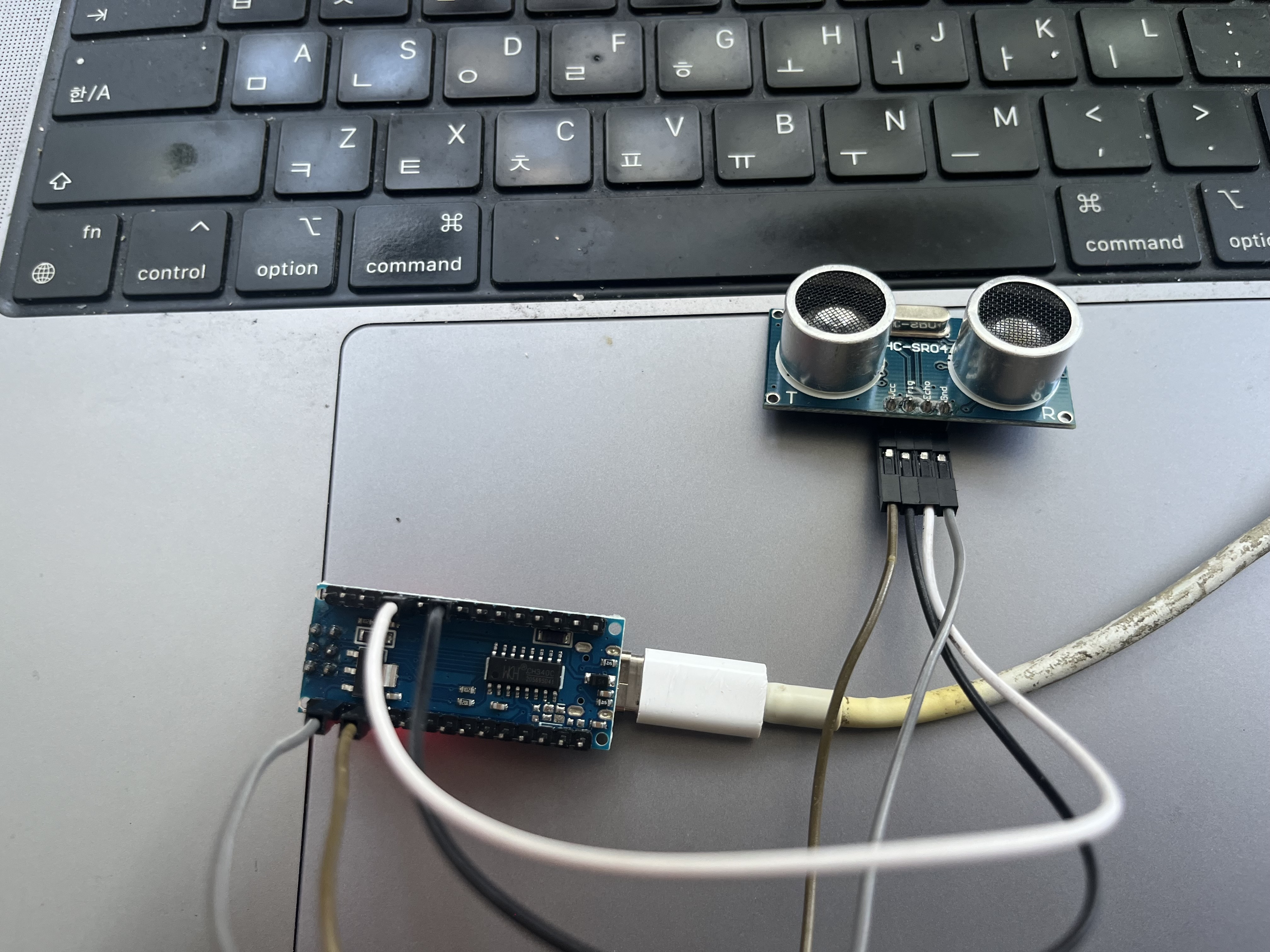
Start with very basic setup
Not using Breadboard yet
HC-SRO4 direct to nano
grnd - >> grnd
echo - >> d2
trig - >> d4
vcc - >> 5v
(I don't understand these connections, and how will add more connections later)
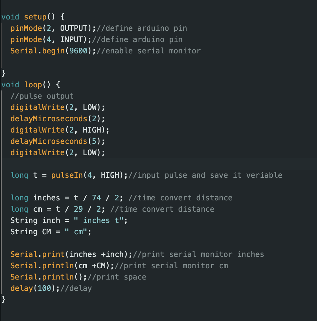
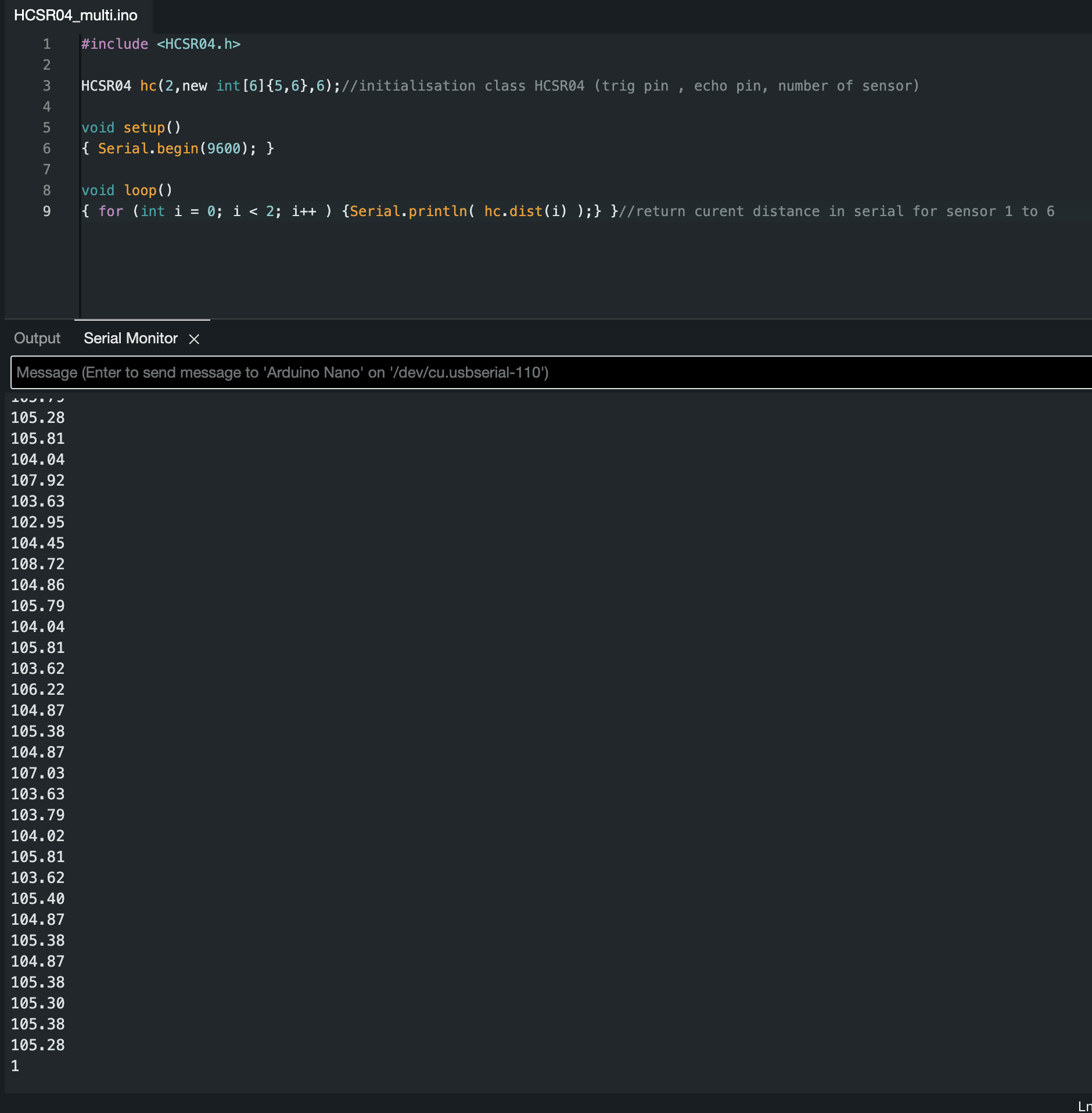
Arduino code (generic)
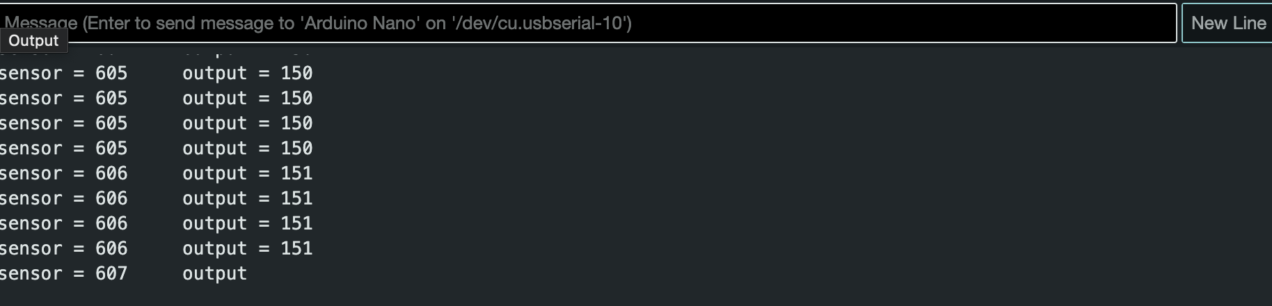
output
Questions:
What does sensor data mean?
What does output data mean?
Why does output data not change ver much when I move around the sensor.
(keep in mind that I have a lot of other code- output does not change very much using different distance math)
I should at least understand how pinmode relates to board - and how 'long' related to distance
//
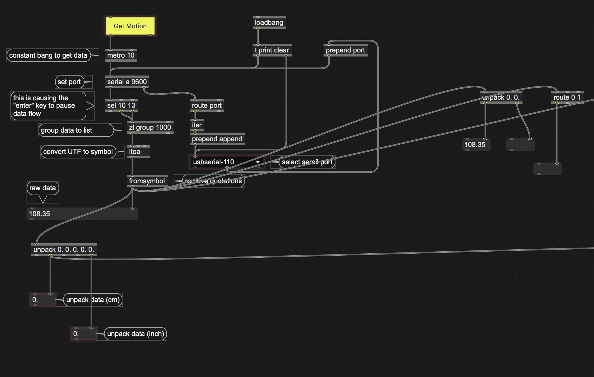
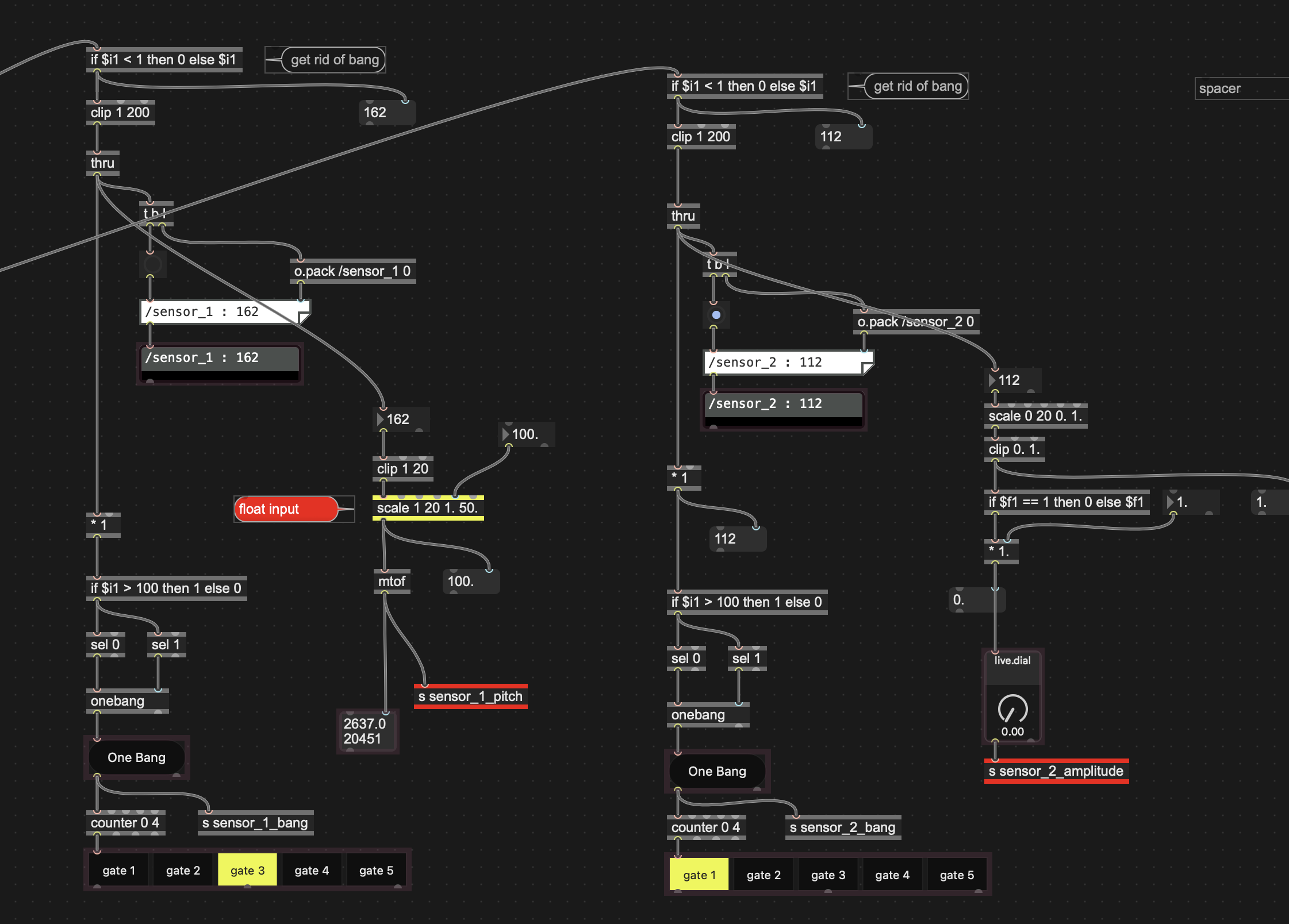
Max code
My laptop has 3 usb-c ports.
Max only recognizes 1 of them. (usbserieal-110)
This code works to get a onebang, only if I isolate the sensor so that there is a tiny peep hole to sense motion.
But this code seems like a giant hack on my part
//
Please explain what is happening with the ultrasonic sensor and best way to unpack in max.
Thanks
//
***Ok. later, After understanding one sensor - then add I will add breadboard and second sensor

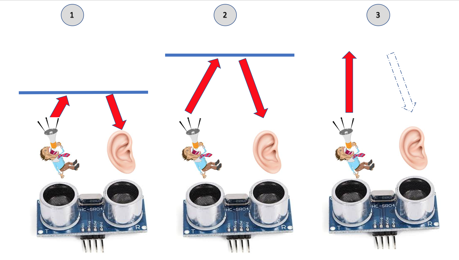
Basically, HC-SRO4 is a radar.
One of the cylinders, the one linked to "Trig", sends out pulses of ultrasounds and the other one, linked to "Echo", listens to their echos. The sensor performs elapsed-time calculation.
If there is an obstacle just above (1), the time between transmission and reception will be short. If the obstacle is farther (2) it will take longer for the echo to reach the listening cylinder. If there is no obstacle (3), there will be no echo.
The Arduino code is supposed to define the length of the pulses and to convert the time (ms) into distance (inches, cm ...). This is done by providing the air-speed at a given temperature as a constant. Depending on what your needs are, this conversion step can be skipped and only raw values may be necessary.
The code you are providing does not correspond to the output screenshot : we should at least see something like Serial.print("sensor") and Serial.print("output") somewhere in the Arduino code, so it is complicated to figure out.
Have you double-checked that Trig and Echo are correctly wired (respectively to 2, output, and 4, input, pins) ?
Several sensors can share the same Trig pin, but must be connected to their own Echo pins.
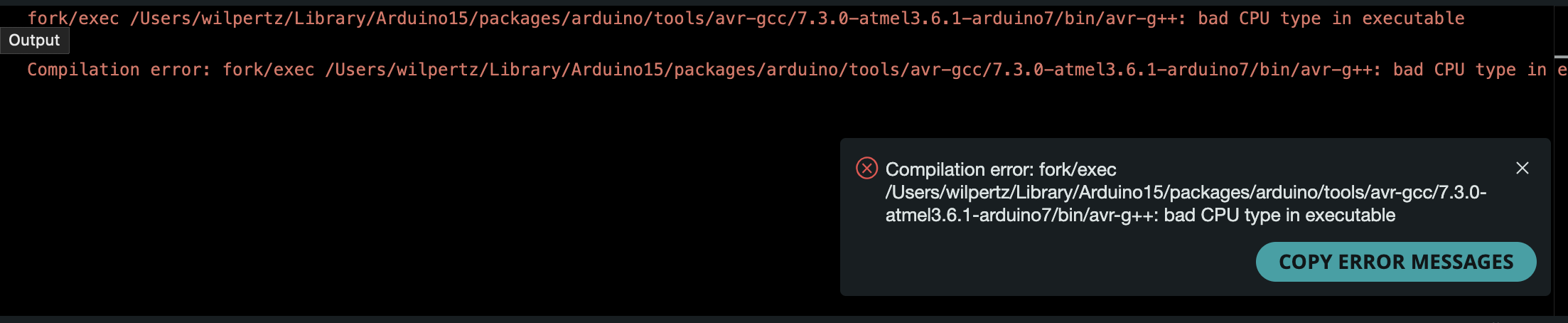
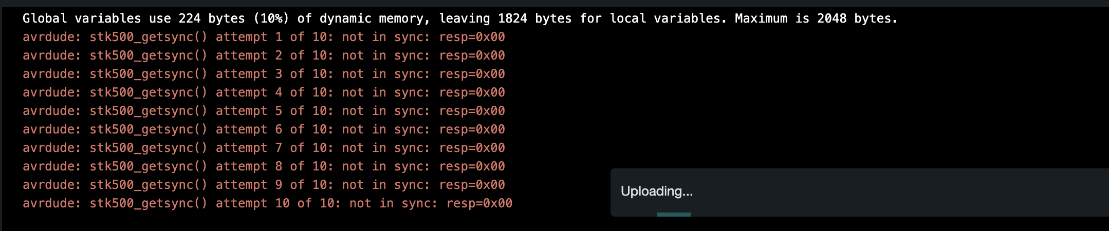
I don't think my code is uploading.
I get this error.
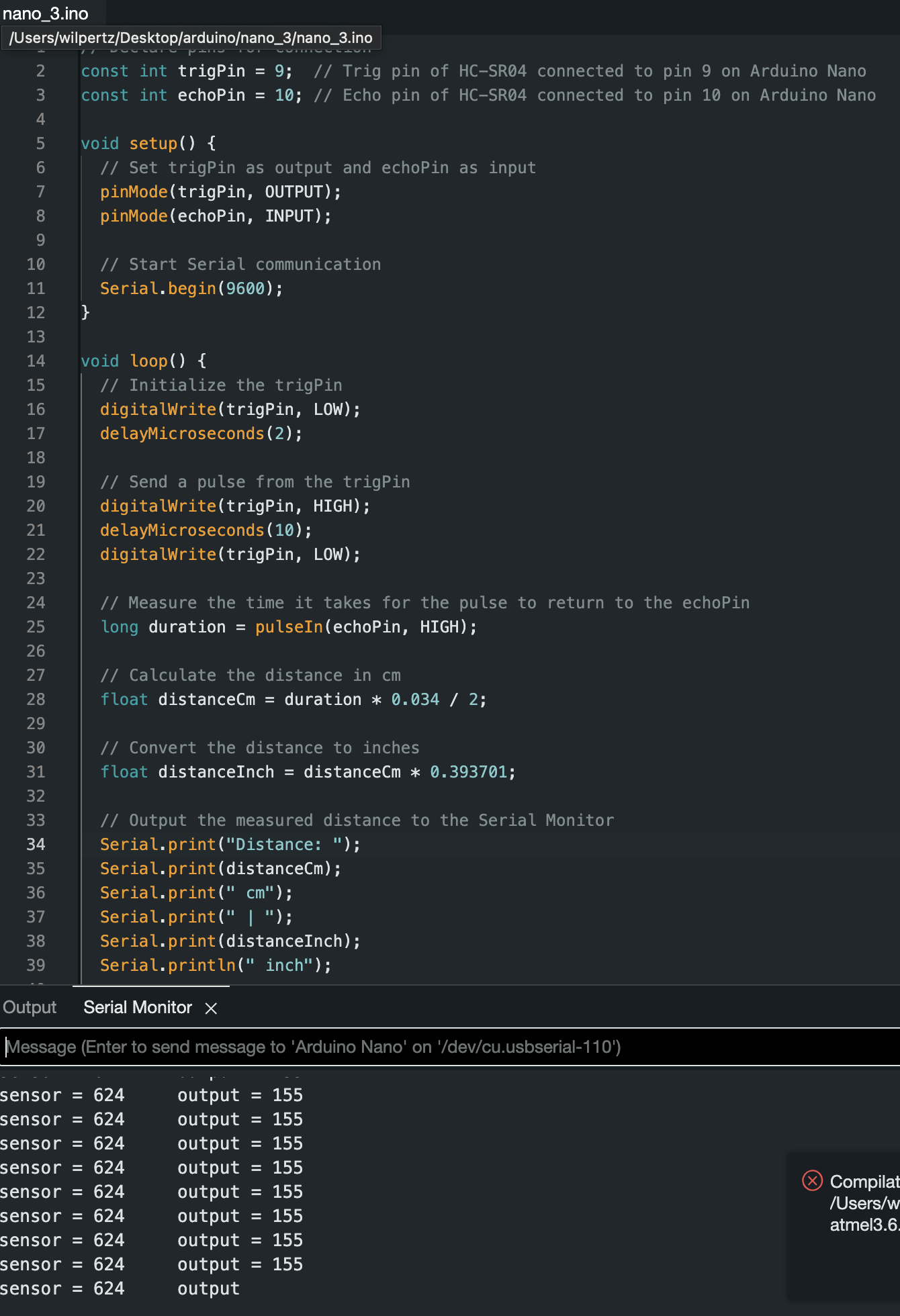
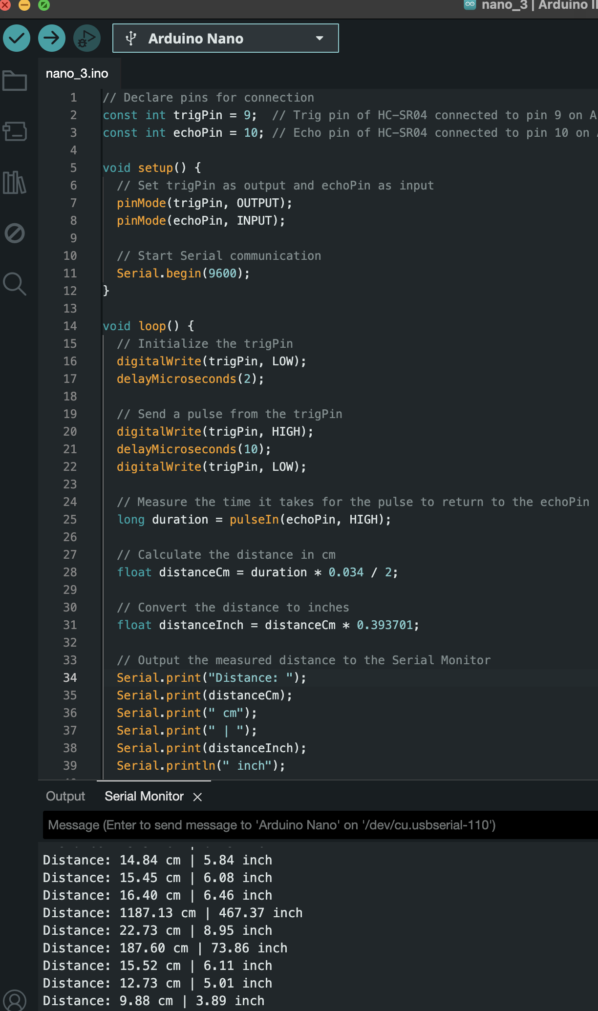
Here is a different code i was given by DIY shop is Saigon.
trig to pin 9
echo to pin 10
this code should work fine - I am beginning to understand it.
not printing sensor though
ok. looks like I needed to install Rosetta.
now getting this error when trying to upload code
Try this one (very basic, no conversion & works here):
const int trigPin = 5;
const int echoPin = 6;
long mes=0;

void setup() {
Serial.begin(9600);
pinMode(trigPin, OUTPUT);pinMode(echoPin, INPUT);
digitalWrite(trigPin, LOW);}

void loop() {
measure();
Serial.println(mes);
delay (100);}

void measure(){
digitalWrite(trigPin, LOW);delayMicroseconds(5);
digitalWrite(trigPin, HIGH);delayMicroseconds(10);
digitalWrite(trigPin, LOW);
mes=pulseIn(echoPin, HIGH);}
Trig <=>5 and Echo <=> 6 (you may change at your convenience and update code accordingly).
Make sure you select the appropriate board and port before uploading

Check Serial Monitor.
Fully Close Arduino IDE before trying to get data onto MAX.

you will find all needed infos there
download this lib
thanks.
I saw that thread already.
1 sensor working great now.
should be able to figure multiple sensors on my own
looks I managed to get 2 sensors working using the ultrasonic lib
can't figure out how to unpack in Max
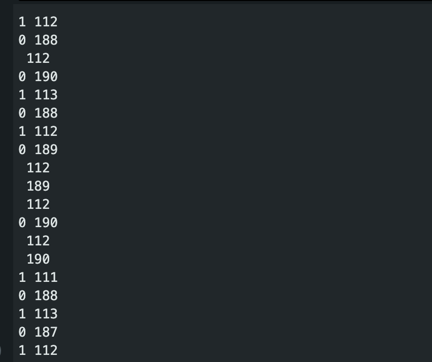
you need to print id , space , then value.
on the link I posted there are examples showing both arduino code and max patch.
this line :
HCSR04 hc(2, new int[8]{3, 4, 5, 6, 7, 8, 9, 10}, 8);
means 8 sensors (bold numbers) and sensor pins in brackets.
2 is trigger pin.
Your line states 6 sensors, but ony pins 5 & 6 ?
take my code from there (modified for you need):
#include <HCSR04.h>
HCSR04 hc(2, new int[8]{3, 4, 5, 6, 7, 8, 9, 10}, 8);
unsigned long Sens[8] = {0,0,0,0,0,0,0,0};
unsigned long exSens[8] = {0,0,0,0,0,0,0,0};
void setup(){Serial.begin(9600);}
void loop(){for (int x = 0; x < 8; x++) {Sens[x] = hc.dist(x);
if (Sens[x] != exSens[x]) Serial.print(x); Serial.print(" ");
Serial.println(Sens[x]); exSens[x] = Sens[x];
}
delay(100);
}
insert correct number of sensors and their pins,
then reduce arrays Sens and exSens size to your number of sensors.
loop for (int x = 0; x < 8; x++) also needs correct value, for example <6 if 6 sensors are in use
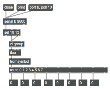
in Max you unpack using route
If you need faster readings, you can reduce delay(100);
and maybe increase baud rate in both Arduino and Max.
to 57600 for example
Just post if you need further help.
Thanks. Charmed!
how do I convert this
void loop(){for (int x = 0; x < 8; x++) {Sens[x] = hc.dist(x);
to decimal (cm not inches)
now getting whole numbers 1 2 3 112 113 etc
what about in between 1 1.1 1.2 1.33 33.33 33. 34 etc
//
only 2 sensor for now working fine
#include <HCSR04.h>
HCSR04 hc(2, new int[2]{5, 6}, 2);
unsigned long Sens[2] = {0,0};
unsigned long exSens[2] = {0,0};
void setup(){Serial.begin(57600);}
void loop()
{for (int x = 0; x < 2; x++) {Sens[x] = hc.dist(x);
if (Sens[x] != exSens[x]) Serial.print(x); Serial.print(" ");
Serial.println(Sens[x]); exSens[x] = Sens[x];
}
delay(100);
}
would like decimal
goal to refine numbers at short distance
Hi Will,
hc.dist output is allready cm.
If you want float output,
change array definitions from unsigned long to float.
float Sens[2] = {0,0};
float exSens[2] = {0,0};
I am sure you can deal with max part once you get input from arduino ok,
just one remark - scale object does not clip.if you set input range 0 - 20 and receive 100
you know what you get at output, right ?
Thanks for float update - working sweetly
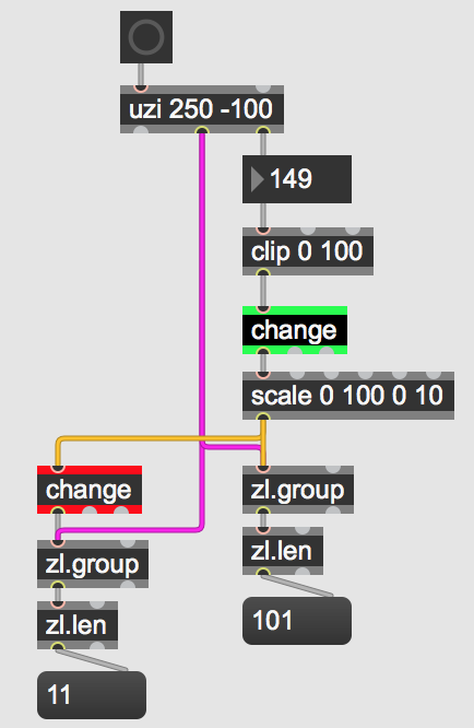
just one remark - scale object does not clip.if you set input range 0 - 20 and receive 100that's why I am playing around with different [clip * *] --> and [clip * * @mode 1] might come in handy for certain situations - if nothing happening within a certain range then zero

for hardware controlllers and GUI elements you almost always need to use clipping in addition to scaling, simply because of their limited data rate. you would otherwise never reach the min and max when moving things fast.
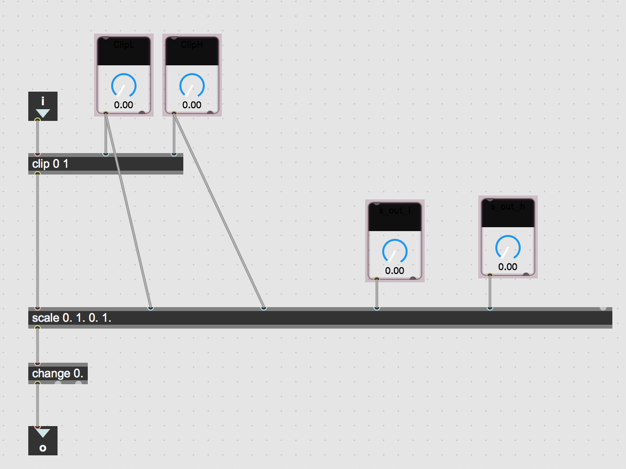
an abstraction for clip-change-scale should be in everyone´s toolbox, possibly with additional inputs for the 2 later processes.
Thanks ROMAN THILENIUS
change between clip - scale
abstraction or module - toolbox updated
change object should be allways at the end of all value manipulating objects.
clip should match scale input range.
Yeah. Makes sense.
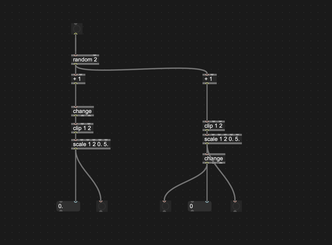
why would you not use it as early as possible?
I think ROMAN THILENIUS is correct.
unnecessary repetitions calculated if change is last
what if scale 0 100 0 10 ???
what help would change before scale offer ?
Understand, if you want to be sure that you have no repeated values at some point in the chain, insert change THERE.
or at 10 places if you want.
You were talking about "tool box" - means something universal, not only suited for that particular case
Thanks
Put [change] where it needs to go when it needs to go there.
what help would change before scale offer ?that you do not process things you do not need anway.
the input of a sensor, encoder or the mouse data from a GUI object always have a limited precision and so it should never happen that two different inputs to the [scale] produce the same output.
we just dont want the min and max value not to be missed (and not to repeat) when the input value is out of range.
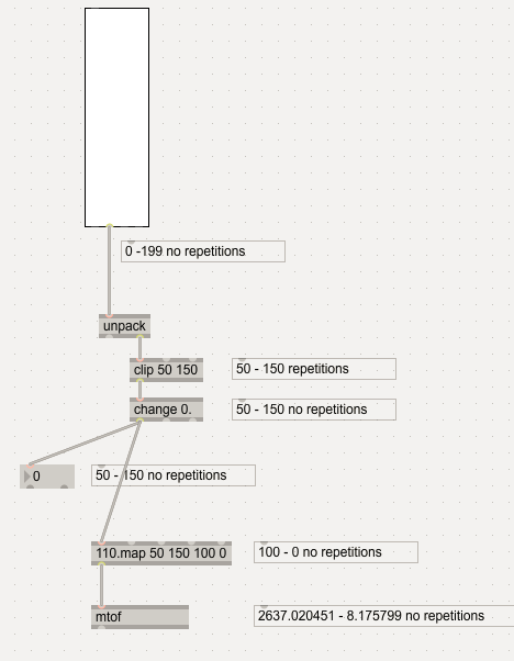
repeating values are only produced by the [clip], not before or after. but maybe i just dont see such cases?
I guess so ...
which change object does the job at the end ? green or red ?
yes if you scale in int mode, then of course. but where would this be correct? :)
but it is interesting that i have never used or needed this until now. i mostly do not insert #1 #2 directly in objects (and even 110.map is float-only no matter the arguments, because i´ve never needed int mode for anything.)
otherwise, as you know, i totally agree upon "as generic as possible".
I've seen scaling ints mostly in midi and arduino projects, where floats are not usable
in most cases.
even if you keep floats till dead end, one has to round and insert change
before sending values.