
Creating OpenGL mesh object from two audio waves in real time

Hi folks
A long time I played with capturing the stream from two audio waves with known wavelengths and drawing them as lines in real time. However, although they looked like mesh objects, I was unable to convert them to real mesh objects. That is, I could convert them to OpenGL mesh objects, but the resulting object has polygons in a spiral, whereas one really wants a blob-type mesh so that one can apply materials to the mesh object properly.
Thinking about it again recently, I realized I was going about it the wrong way. Instead of making a continuous line for each of the two audio sources separately, I should be stuffing each two synchronous values from the audio source into the same {x,y,z} mesh coordinate.
I started to figure out how to code it, but I'm not quite sure how to set individual mesh coordinates. I'd rather use a FOR LOOP in jit.gen I guess, processing say 512 samples from a stereo audio buffer for each video frame. But who exactly do I set individual mesh coordinates in an OpenGL mesh?
Well I started lookiont at jit.fill, but I can't find any information on how to order the data in a jit.matrix, and the git.gl.mesh object has over a dozen attributes for @draw_mode, on which I can find no documentation.

Hi.
For a nice "draw modes" explanation, see the following tutorial.
Anyway, I'm not understanding what you mean by "the resulting object has polygons in a spiral, whereas one really wants a blob-type mesh so that one can apply materials to the mesh object properly."
jit.gl.graph receives a matrix with the geometry and draws it as a 3D mesh. Of course you can use other jitter objects, even jit.gen to draw it yourself according to your intended purpose.
Can you explain a little more your intended geometry?
Thanks! Well when I wasd piping the signal in with jit.catch~, with left channel to x and y channel to y, it puts each point in the buffer sequentially until it fills up, so you get a spiral line strip. So what I really should be doing is building a series of strips with overlapping vertex points from the last ring, I guess.
.png)
The jit.graph object puts the rings at equidistance on the z axis. What I want is to make a blob with the second audio channel controlling the z axis. So the strips also have to wrap back to their start.
Like a ring waveform? jit.gl.graph also has a "@radial 1" mode. If it's something more specific, you would have to configure a matrix to represent the intended geometry. I'll try to post an example here.
Not a ring, I was thinking of a blob. It would be a sphere if both waveforms are sines. It also requires a variable matrix size across time to accommodate changes in frequency, unless the waveform is pitch shifted to fit the same frequency.
I got a jit.gl.mesh coordinate matrix input to draw SOMETHING, but I still don't understand how to arrange the data in the input jitter matrix. I tried putting the x y z coordinates in an array in one plane. That doesn't appear to work except for drawing lines. Maybe each coordinate is in a separate plane, or maybe each axis is in a separate plane. This is going to take some more trial and error.
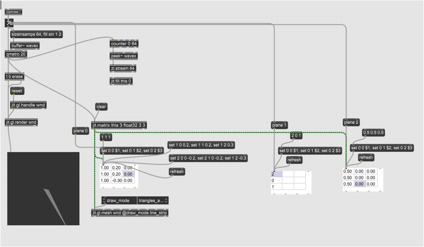
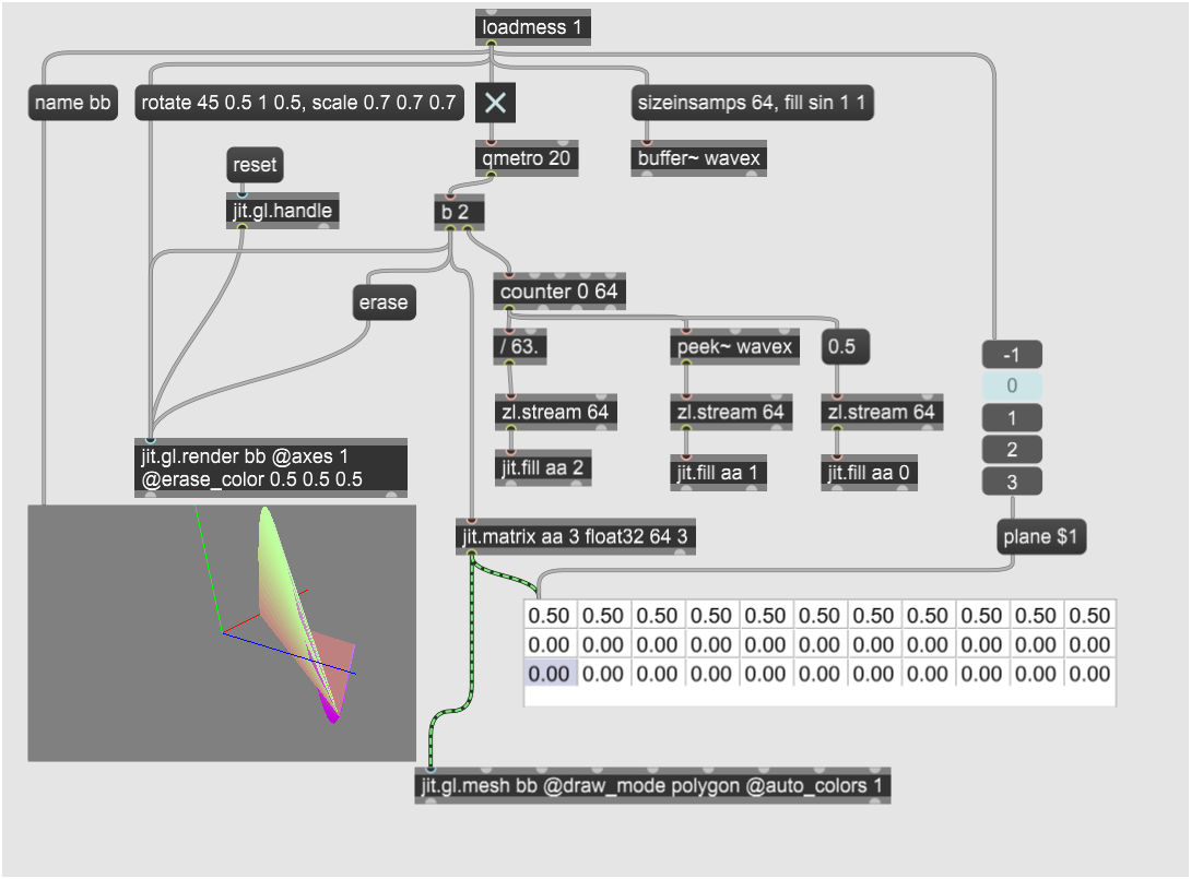
I finally drew a polygon by setting matrix values manually, Im not sure exactly how, but it's in the Z axis so you have to twiddle the window handle to see it. So none of the tutorial objects supplied draw like it says they are going to, which is possibly because it relies on some undocumented feature that has changed. which could also be the ordering of point data in mesh coordinates. But it appears from what it says that the x, y, and Z cordiantes are in three separate planes, with the values for each successive point in successive rows in the matrix, with each column drawing a separate shape. That would explain why my experiment is in the Z plane, because I didn't set any third-row values yet. But now I need to take a break from it and start from scratch again.
On the third try, I can draw ordered points,, and from combining bits of this from my first I attempt, I can finish my project. Being deaf, I won't be able to design it for real-time audio. Probably I'll make some harmonic wave generators to create some interesting non-random organic shapes with ripples slowly moving across them. Thank you for the assistance.

i dont know if you know this but the message plane -1 allows you to see all the planes at once in a jit.cellblock, in this case x y and z
also in gen you can use the cell operator to access individual points, which might help you?
Than ks Tikoda, I didnt know about the cell operrator in gen, that's a really big help. I looked at various draw_mode settings, and it seems I need the polygon value to texture the triangles rather than color the edges, so it looks like I just draw each triangle in a separate row, which will be easy with a gen~ FOR loop :)
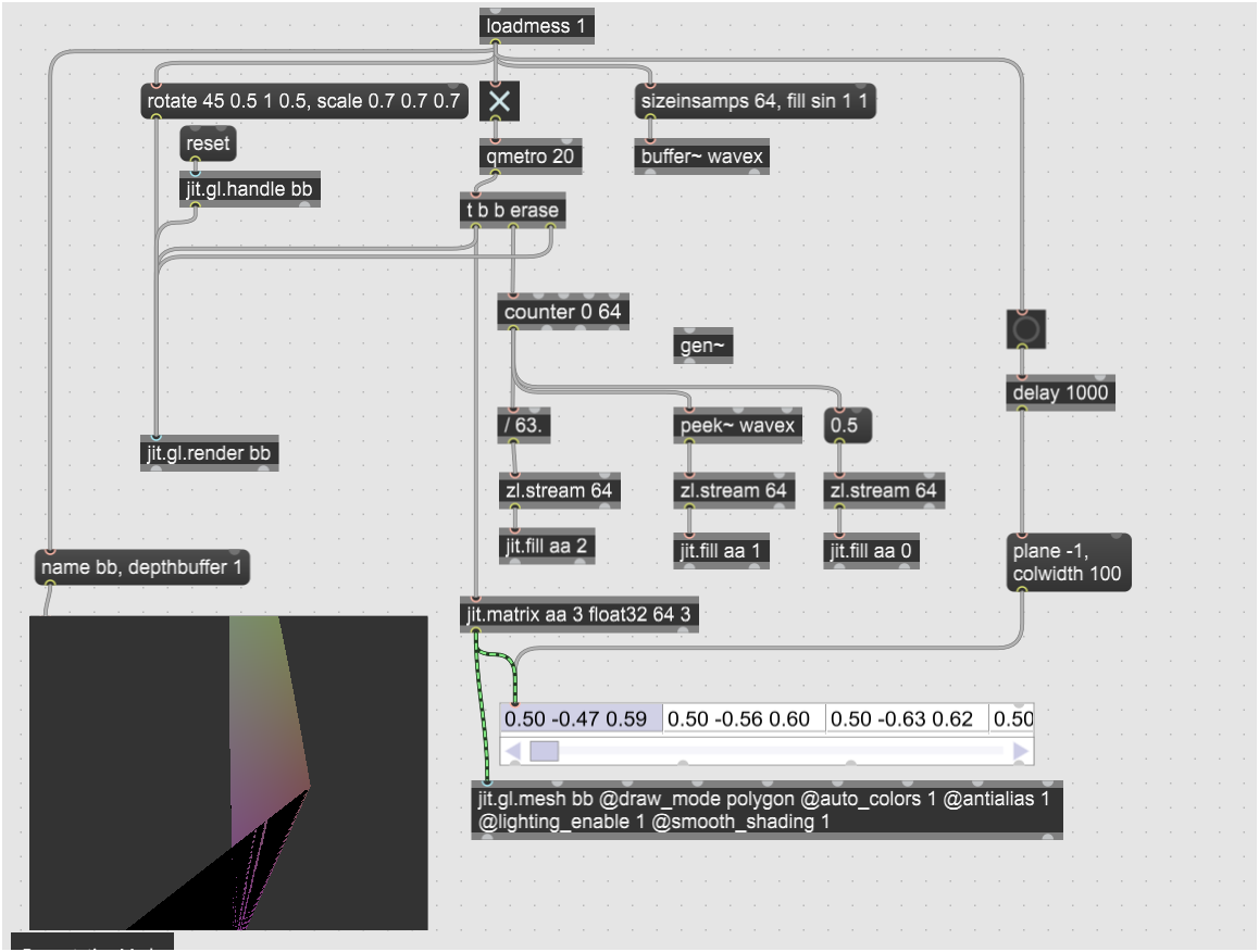
Here's an example modulating a sphere shape with 3 different frequencies captured by jit.catch
By the way, I couldn't get the planes to display in multiple rows in jit.cellblock, but I was just trying to figure out if the jit.fill was working. I did merge the first piece for putting a sinewave into a buffer into this prototype before writing any gen~ script for it.
It transpires there is a new appendix B in the Jitter Reference Tutorial that contains the information I was looking for. What I was actually having trouble with was plane 12, which I should be able to figure out now.
Thanks again for the help.
I could get the "planes -1" working on jit.cellblock by setting colwidth manually after setting a 1000 msec delay from loadbang. I still have axes disappearing which I remember is an old problem and I guess I will be replacing them with my own gridplanes manually again.
Pedro, thanks for the contribution, but I was looking for a mesh shape not nurbs, thanks again )
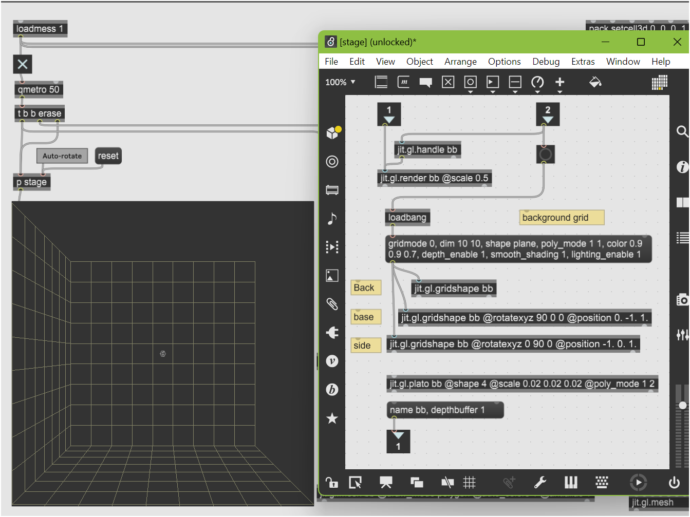
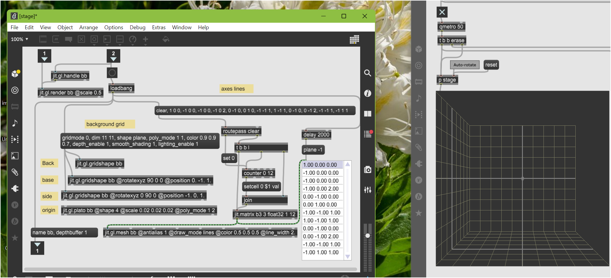
I added my fundamental subpatch for drawing a stage again, here it is. It includes the simplest possible preconfigured objects for a stage, with the grid set around -1~+1 for width and height, and 0~-1 in depth. scaling the render context by 50% so the grid aligns with the viewport edges.
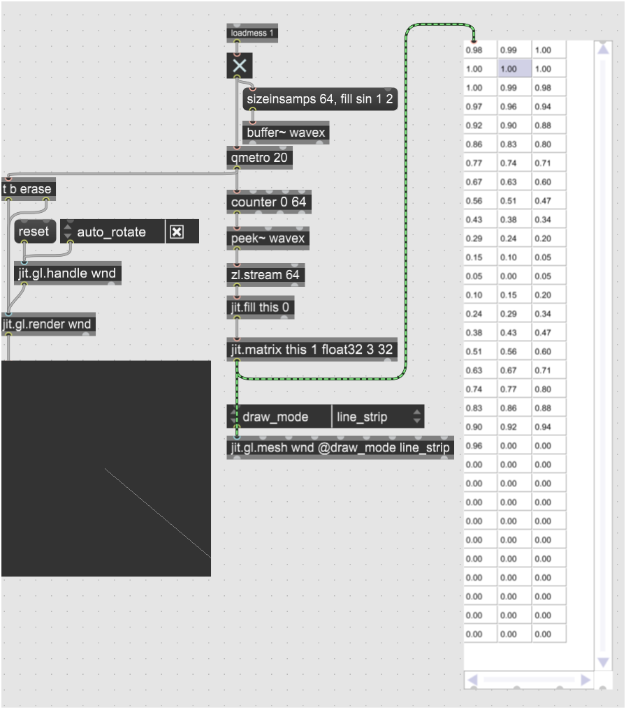
Now I can manually draw individual lines into jit.gl.mesh. Looking in the forums, no one had done this before. When draw_mode is set to "lines," one has to set the beginning and end point of each line as consecutive pairs of points, one point in each row, with the x y z coordinates in the first three planes of a jit.matrix object, then pass the jit.matrix into the first input of jit.gl.mesh. Here I drew two horizontal lines on the back and side axes of the stage.
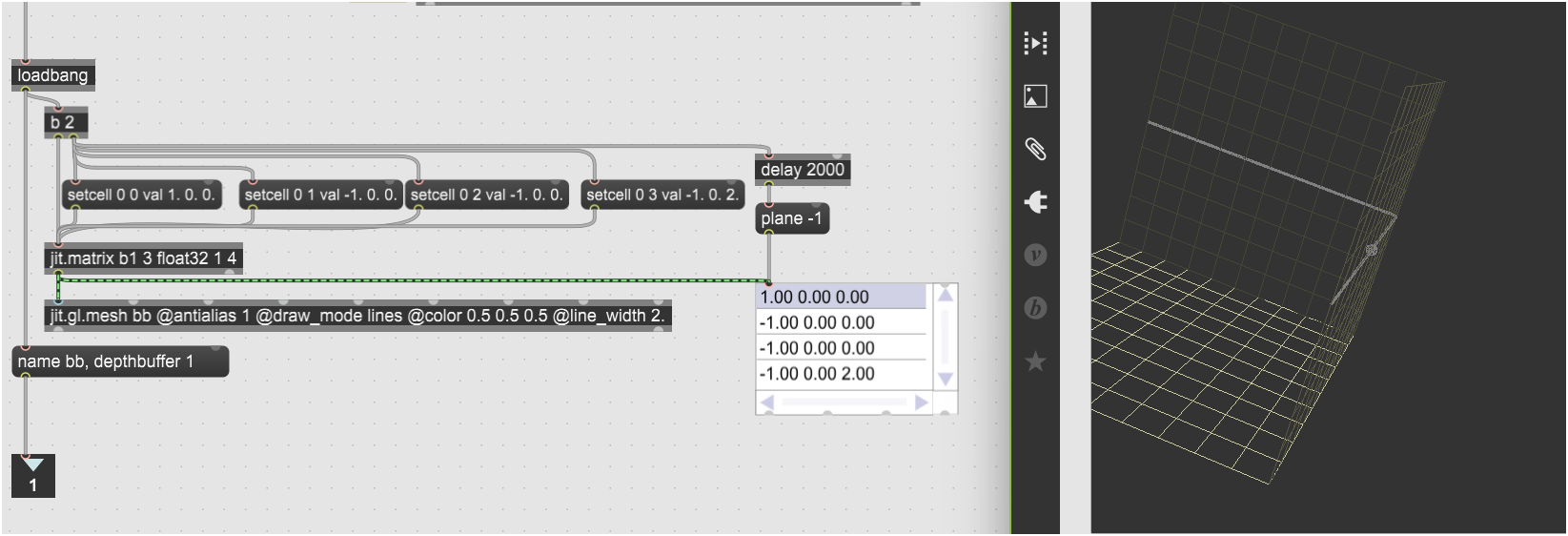
This stage adds an iterator that converts lists of [x y z] coordinates into an OpenGL mesh (in this case, the stage's axis lines). The message at the top right generates 12 lists, which are each fed into SETCELL messages for jit.matrix, which then passes the matrix into a jit.gl.mesh object for rendering. So now I can use the same iterator to generate meshes from wave sources.
For audio I am importing my BEAP waveset oscillators, made with my synthcore v1 library. The v2 library on my site at https://yofiel.com has antialiased saw and triangle oscillators too, so I plan to update the BEAP code later.
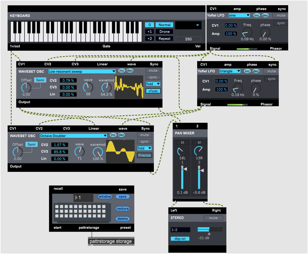
The waveset oscillators require that the patch be saved and opened from the same directory as waveset_all.wav is saved, which is in the zipfile below.
So now the BEAP oscillators and gen~ object are in place to draw triangles.
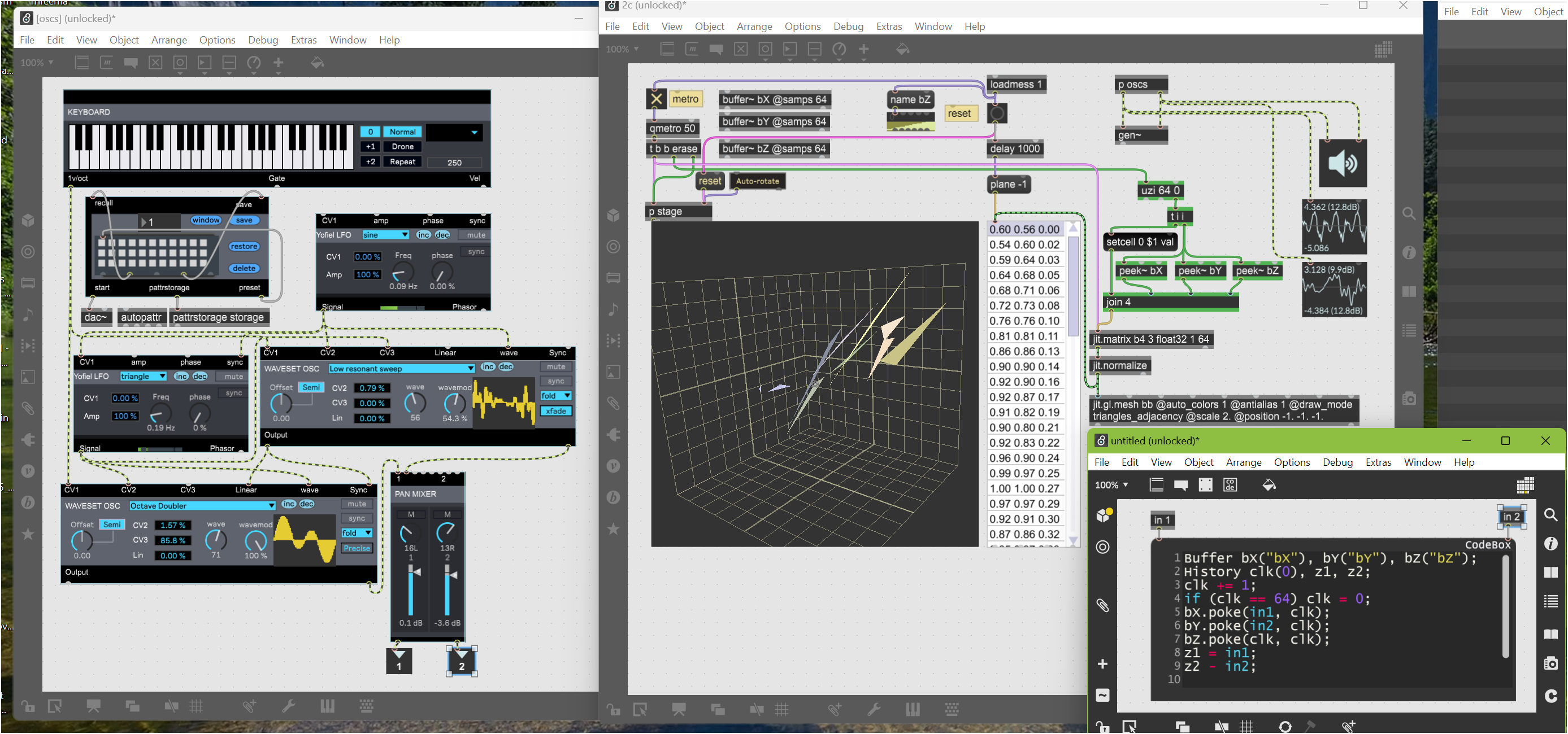
Unclickable elements are hidden when the patch is locked. The stage is slightly adjusted so that the grids surround the origin, from (-1, -1, -1) to (1, 1, 1), and the camera repositioned for a default orthogonal view. You'll need the zipfile from the prior message as it described for the oscillators to work.
Currently the generated mesh is normalized and translated to fit in the viewport, which I will be adjusting so that the mesh grows and shrinks with changing amplitude. But I still need to feed the CV voltages of the oscillator pitch frequencies into gen~ as well so I can scale and rearrange the signal data into triangles or quads. So I am thinking actually it needs another two input buffers which I resample to fit a particular number of mesh points, which will need to capture audio data down to 50msec so 20Hz waves display properly.
Then I'm thinking the easiest thing to do is draw triangles with shared vertices using history operators in gen~ to capture the last edge. I think that means the output buffer needs to be triple the number of sampled points.
My plan is to make two hemispherical shapes, one for the upper half of the signal, and one for the lower half, then position them one on top of the other one upside down, which will simplify generating the normals for the mesh polygons, because all the faces will be on the same side of the mesh. That's before adding materials, an enhanced camera stage with secondary view with adjustable lighting, and adding the analog oscillators to the BEAP gen~ code. then I guess I put FFT onto input audio to extract the fundamental frequency so it can work with other audio sources.
There are examples of people using a similar method to place points to draw speaker positions for multi-channel audio set ups. in this case they used a coll to write the point positions.
Not sure I totally understand what you’re aiming for here but I’m curious to see the result!
Is there a reason you’re not using jit.catch to turn the audio into matrix data? is this uzi/peek list method doing the same thing but Just on one plane?
the problem I had with jit-catch is that the data is not in the right order for creating surface polygons.
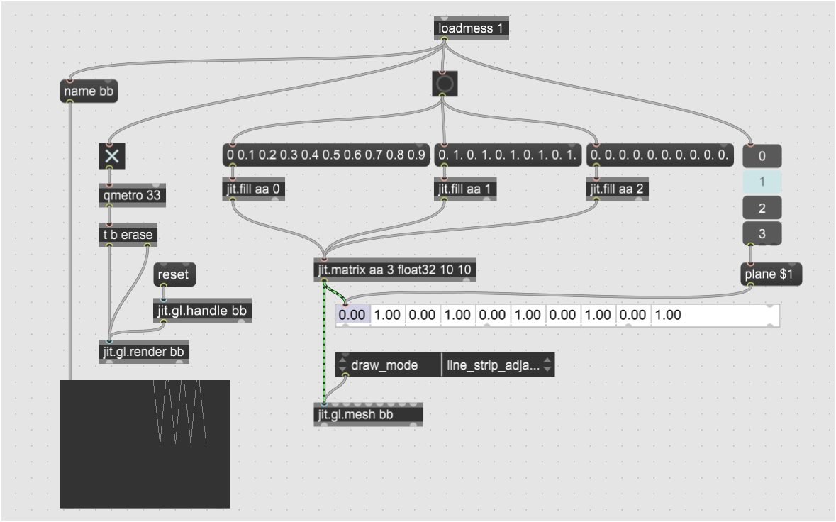
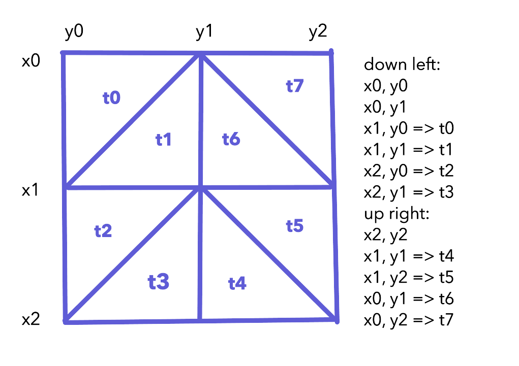
As a next step which makes something useful in the process, I am thinking of changing the height of points on a regular 2D mesh by combining the left and right channels. The leasdt number of points are possible with tri_grid, in which each concsecutive point forms a new triangle with the prior two points. So one can tesselate ordered points to form a 2D mesh like this, generating 8 triangles from 11 points. Drawing each triangle separately is simpler to program, but it would need 24 points.
So for the waves to move smoothly on the display, the mesh has to generated from an integer number of waves at the fundamental frequency of the input signal, with the wave samples starting and ending on zero crossings.
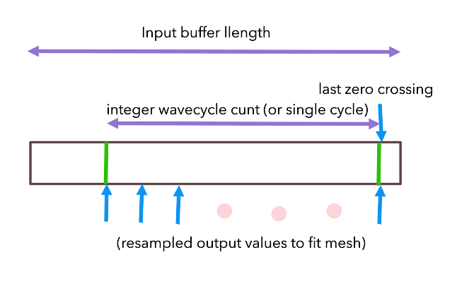
As the input is currently a synth, the input frequency is known, so the output is taken from the input buffer truncated to the following length from the first zero-crossing sample:
waveCnt = floor(output_buffer_size / input_freq);
sampled_buffer_length = waveCnt * input_samples_per_cycle
From which the output samples to generate mesh point values are taken, for example with a 1024-point quad mesh:
output_sample_interval = sampled_buffer_length / 1024So samples are taken from the input buffer's last zero crossing backwards, at output_sample_interval for wavCnt samples.
A 1024x1024 mesh is 1M points for each frame, which at 25Hz is 20 points per microsecond, so it probably needs some serious parallelization and code optimization. But that captures audio waves down to 25Hz at standard audio rates. I guess I should make the mesh size a variable lol.
A simpler approach would simply be to resample from the last single input wavecycle, and only display one wavecycle regardless of input frequency. So I'll start with that and a 64x64 mesh so as not to hit performance issues, and write the code so I can enhance it later.
From that, I can construct a loop in gen code to resample the input buffer values so the wave fits exactly on the mesh length. if I got it all right., then the waves will fit exactly on the mesh. I don't think spline interpolation between the input samples will make enough of a difference, and either linear interpolation or the nearest sample will be enough, but I'm not sure.
Thus my draft code for resampling is this. I still have to adjust the output sample order for correct mesh tessellation:
Buffer bX("bX"), bY("bY"), bZ("bZ");
Data inL(50000), inR(50000);
History idx(0), odx(0), inLz(-1), inRz(-1), zCrossL(0), zCrossR(0);
Param qmetro(50), freqL(20), freqR(440), bufLen(64);
l0 = dcblock(in1);
r0 = dcblock(in2);
idx += 1;
if (idx >= 50000) idx = 0;
if (l0 >=0 && inLz < 0) zCrossL = idx;
if (r0 >=0 && inRz < 0) zCrossR = idx;
inL.poke(l0, idx);
inR.poke(r0, idx);
inLz = l0;
inRz = r0;
wavelenL = samplerate / freqL;
wavelenR = samplerate / freqR;
ivalL = wavelenL / bufLen;
ivalR = wavelenR / bufLen;
odx += 1;
if (odx >= bufLen) odx = 0;
u = 50000 - (zCrossL + odx * ivalL);
v = 50000 - (zCrossR + odx * ivalR);
if (u < 0) u += 50000;
if (v < 0) v += 50000;
w = inL.peek(u);
x = inR.peek(v);
bX.poke(w, odx);
bY.poke(x, odx);
Of course this is filling the output buffers continuously, when they only need to be filled at the qmetro rate for the screen refresh, but it gets me going.
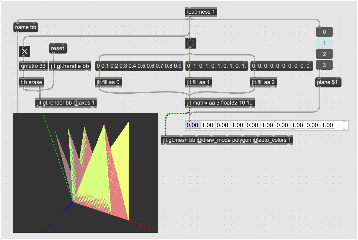
The resampling buffer to fit a single-cycle input wave onto the OpenGL mesh is basically working. Here I set the draw mode to "triangles" with 64 points. but I'm not sending duplicate points, so they aren't joined together.
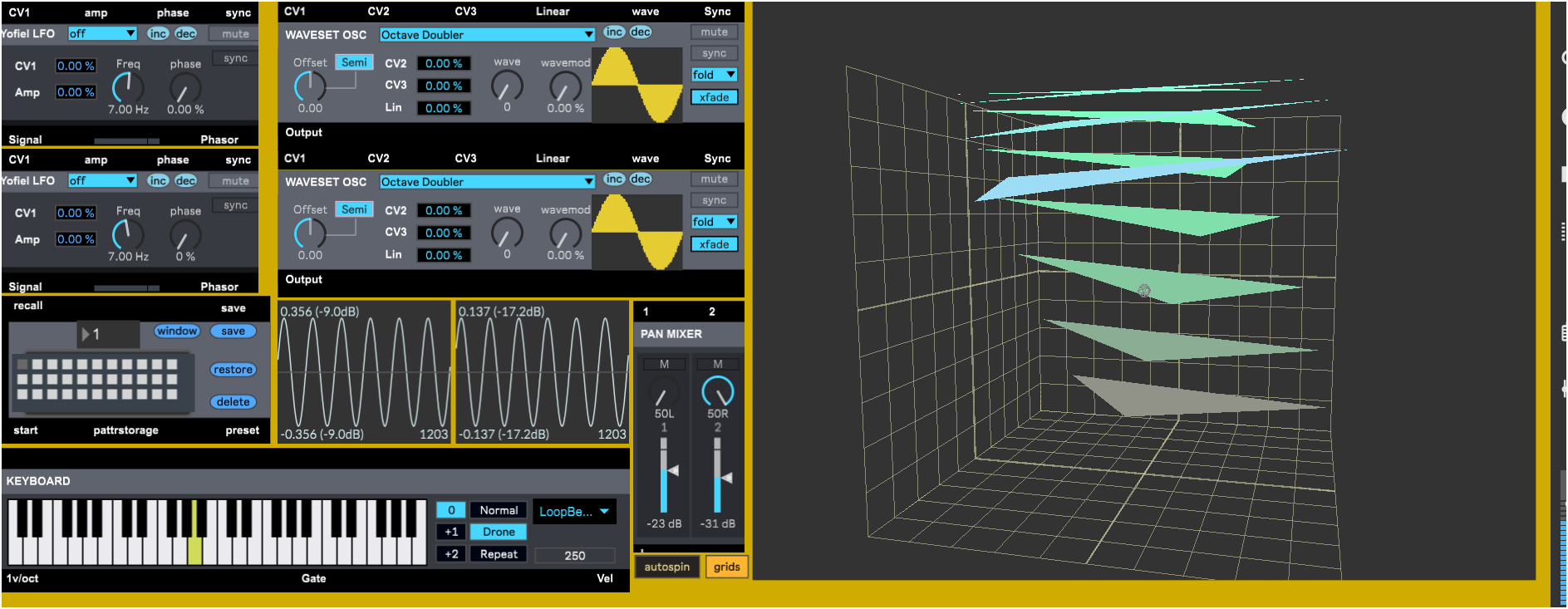
So in view of the lack of interest in anything except telling me what to do instead, I dropped the project. Here's the final code for the above screenshot. You may try to persuade me to do something else, but at this point I'd want money lol, I'm retired and I don't need it so no worries. Cheerio )
Hi, Ernest. I was following with curiosity the documentation of your process here. I like reading these topics that are written as a sort of public personal journal on a particular project.
I would like to add that the perceived lack of interest on a particular topic in a forum can be just that, perceived. And sometimes, even if there's no feedback being given at the time of writing, there's always someone down the road that will find it as invaluable information. So, thank you for your efforts!
Well thank you for saying so. To be candid, the only thing people have ever actually used is my gen~ code library. I don't think anything else I ever shared was even downloaded.
I always learn a lot of new ways of thinking from your patches, just had a chance to open it and its definitely interesting. I'm curious if you had a vision of how the visualisation would look, and if this is it? It isn't what I imagined from your earlier descriptions.
Knowing your ability with gendsp code I wondered what would you achieve with jit.gen and thought that was where you were heading. Obviously don't do it on my account but... go on.

thanks you so much Ernest

Very valuable and thank you for sharing your knowledge and insight with the community. I learned something today