Frequency vs Phase Modulation
Hi folks,
I'm trying to get a better understanding of the basic differences between Frequency and Phase Modulation and am wondering if I have the following correct. In both cases, the Carrier is at 200Hz with the Modulator at 300Hz. I adjusted the Modulation Index for FM to 3 to get the two sounding somewhat similar. Am I approaching this correctly? Is there an actual Modulation Index for Phase Modulation. I know the Phase input for cycle~ goes from 0. to 1., which I've done with the offset on the Modulator wave. Is there another value that is used for Modulation Index? Thank you for your assistance!
for the phase modulation part you would first of all connect a phasor~ to the right inlet of cycle and nothing to the left inlet.
phase modulation (as in DX-7) refers to the phase accumulator.
note that the "phase" you want to modulate would be the left inlet of cycle, too. if something is cycling and has a frequency input, it has a phase accumulator built-in.
they should never have called it "phase modulation" IMO, it is totally misleading. as soon as you look at the accumulator as part of the oscillator, it is FM again.
try to use phasor~ & cos~ instead of the cycle~ wavetable and you will see the issue with your current concept. :)
Just going to drop a few things that helped me understand FM & PM better when I was learning them.
All of this (and much more!!) is in Chapter 8 of https://cycling74.com/books/go. I recommend gen~ as a good environment for exploring FM and PM, especially to open up more interesting & unusual circuits, such as cross-coupled feedback FM, or putting filters between oscillators -- the combination of these can produce some remarkably organic/analog sounds.
- FM/PM are very similar, and in many cases practically identical; the main difference is whether the modulation is added to the frequency input of the carrier’s phasor (FM), or to its phase output (PM).
- As Roman says above, it helps to decouple the accumulator from the sine shaper in your mind/diagram/patch. FM goes before the accumulator, PM comes after the accumulator, both are before the waveform shaper (sinusoid or otherwise).
- With FM, the modulator waveform modifies the resulting pitch. With PM, the derivative (rate of change) of the modulator waveform modifies the resulting pitch. If you only use sinusoids, they sound the same, because the derivative of a sinusoid is a sinusoid. But with almost any other waveform, FM and PM no longer sound the same.
- FM/PM produce a series of sidebands, all at even frequency spacing, spread in a way that widens with modulation index/depth, and which depends on the shape of the modulator.
- Harmonicity depends on ratio between the carrier and modulator frequencies; it makes sense (as John Chowning advised in this very forum) to make these both multiples of a fundamental frequency (but also, like most harmonic relations, it sounds great to have them very slightly detuned)
- AM of PM can create asymmetric sideband series.
- Many more complex sounds possible by combining multiple circuits: parallel carriers, parallel modulators (which basically means modulating with a more complex signal), cascaded modulators (giving a fractal-like spectrum) and more. With feedback modulation we can get chaotic noise effects, and we see how to get better control over this by adding a filter into the feedback loop. This gets a lot richer with multiple oscillators and filters in feedback.
- With non-sinusoidal waveforms (which also includes when modulating sinusoidal modulators), PM and FM can start to behave quite differently, because with PM it is the derivative of the modulator that changes the carrier’s pitch. Interestingly we can counteract this by passing the modulator through a filter: FM with a high-pass filtered modulator is the same as PM with a low pass filtered modulator!
- Filters in the loop can also fix the detuning problems of FM and the clicks that can be caused by PM. Honestly I think it would be better if all FM/PM operators included a filter by default.
- When the carrier frequency is zero, PM is simply waveshaping.
- Modulating delay time is another kind of PM (think Doppler shift).
- We can estimate the bandwidth of FM/PM (with sinusoids) and use that to limit modulation index to prevent aliasing. If we want non-sinusoid, we can use an anti-aliasing wavetable oscillator.
- If we want only harmonic tones but smooth glides, we can crossfade between nearest harmonics.
- Adding AM with a window shape can produce vocal acid-like impulse trains.
Hope that brain dump is useful for someone. Much more about it, and examples of all of them, in the book ;-)
(unless graham has to correct me...)
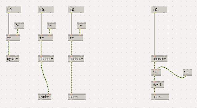
only the right one is PM.
as a result, it wonly works with cyclic stuff, not with live input or longer samples.
note that inside the cycle object there is *drumroll* a phase accumulator.
do not take those + * % too serious, these are only placeholders for "here happens the modulation".

Roman and Graham, thank you so much for this. This is incredibly helpful! I look forward to receiving my copy of the book as well! (Just ordered)
I will attest that the FM chapter in Graham's book is really good. And also the FM chapter in the V3 Cipriani and Giri is really good too. They complement each other well actually. Both are my current computer music reading. :-)
Thanks, Iain. I have Volumes 1 & 2 of Cipriani/Giri, but hadn't gotten V3 yet. Now I have a good reason!
Hey Roman, in your graphic above, is there any real difference between the outputs of #2 and #3?
cos is more accurate, even if you put cycle~ on a really huge size (in max7 and above), but it is also more expensive.
(and cycle~ might develop habits when you change direction abruptly like sending noise into it.)
nope. i am wrong.
it seems to be no longer a wavetable since max7. CPU hunger also tells it.
but if you like we can make up another excuse to use cos? for example it is shorter to type.

Shorter to type and I invariably end up connecting the phasor to the left inlet of cycle~ by mistake at some point and getting frustrated that it's not working! 🤪
yeah you cant get confused by inlets, this is a big pro for math objects.
otoh cycle~ will allow you to use complex harmonic wavetables when needed.
spoilt for choice.
Also, this (older) page is really good. It's by Barry Truax from when he worked on FM at Simon Fraser University here in BC!
https://www.sfu.ca/~truax/fmtut.html
@Roman:
"(unless graham has to correct me...)
as a result, it wonly works with cyclic stuff, not with live input or longer samples."
Since you invited me :-) I guess one exception is continuous modulation of delay lines. If you feed a sine wave into a delay line, and modulate the delay time with another sine wave, the result is mostly identical to phase modulation. (The only exception is that modulation can't go "through zero", since the delay time always has to be positive, but otherwise it produces the same patterns of side bands as phase modulation.) Of course you don't have to stick to sine waves, you can use any sound whatever as the input to the delay. This can create quite an explosion of side bands that can easily cause aliasing, but you can combat much of this by using sinc interpolation on the delay line.
It's basically the same effect as Doppler shift. Put another way: if frequency modulation is like a singer with extreme vibrato, then phase modulation is rather like a singer with no vibrato, but who is moving very quickly toward you and away from you!
when i think about it, you can of course also PM the phase of very long sample. but i would not implement it like that.
but yes of course, live input can only be FM´ed using a tapping buffer and i might have missed what that actually means.
(playspeed of the readhead != "frequency"... live input does not have a frequency)
the actual reason for PM in the DX7 has never been clear to me, it seems like a detour. :)
First off, I want to thank you all for the tips and suggestions. I've been studying Graham's and Gregory's Generating Sound & Organizing Time and learning a tremendous amount. I understand how to do FM and PM where the modulator is non-sinusoidal, and I can do FM where the carrier is non-sinusoidal. Is it possible to do PM with a non-sinusoidal carrier? Is that even a thing? If so, where do you insert the modulator signal? Do you modulate a delay line of the carrier output? Thank you!
FWIW this is covered in a lot of detail in third volume of Cipriani and Giri too. Cross referencing that with the Wakefield and Taylor book helped me a lot for a big FM project for a course.
The reason for PM over FM is that for certain settings the pitch stability is much better. Yes, you can do PM of a non sinusoid, I think the issue (with both PM and FM) is that with a non-sinusoid you get a whole lot of non-harmonic partials very quickly, so most settings just get really damn noisy. But if you're looking for that, go for it! :-)
Thanks, Iain. I've got that text as well, but hadn't gotten to it yet. I appreciate the referral.
Barry Truax's old pages on the SFU website are also great if you haven't discovered those yet!
https://www.sfu.ca/~truax/fmtut.html
Thanks, Iain! Yes, I've read those pages as well! I'm attempting to better understand how something like FM8 works. In spite of its name, it appears to be doing Phase Modulation instead of Frequency Modulation, yet it allows you to choose different waveforms for both the modulator and carrier operators. I've built a gen~ patch that allows me to use different modulator shapes, and I know how to apply FM to different carrier shapes by sending the modulator output to the left input of the phasor object. Where I'm getting stumped is on doing PM with different carrier (non-sinusoidal) shapes. I understand how to shift the phase of a sine wave, but I don't understand how to do that with non-sinusoidal shapes.

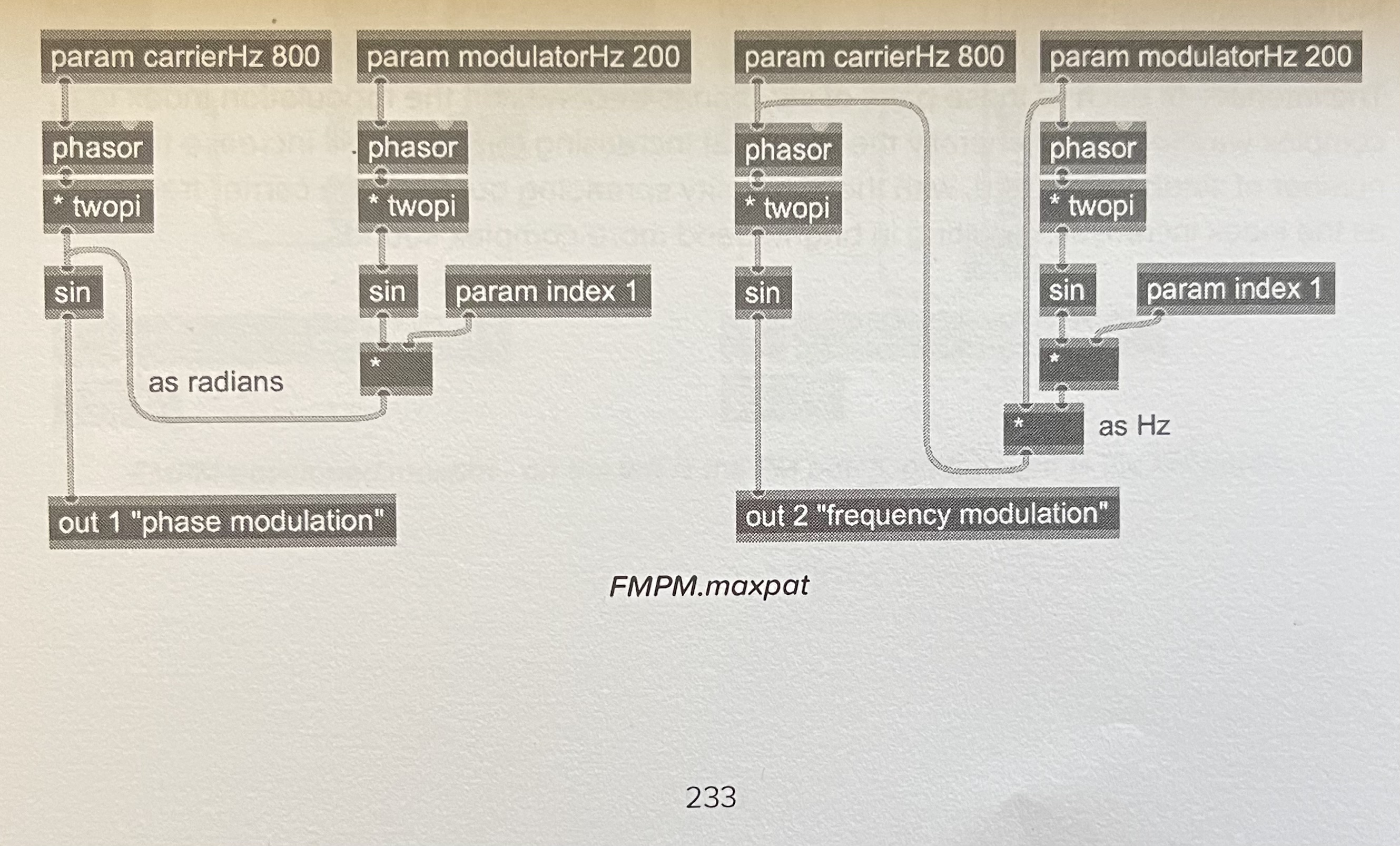
^in your patch above, any modulation you apply after the 'phasor' ops(the two going to the outs), whether before '* twopi' or just after it, will count as 'phase modulation': phasor is drawing the 'phase' of your carrier wave, so you can use phasor to drive other waves, not just sinusoidal(the GO book shows you how to drive other waveforms with phasor), then whenever you modulate the signal coming out of phasor itself, that will be 'phase-modulation'(to do this with mathematical predictability over sideband pitches and finite control of timbre is easier with sinusoidal waves, but if you just want 'phase modulation' itself, it can be easily done by focusing on how you reshape the 'phasor' signal going from 0 to 1 as it drives other waveforms: as an example, put a simple '>' op just after the 'sin' leading to the 'out 2 PM' and instantly, you'll be applying your phase-modulation to a square-wave(not anti-aliased, tho) instead of the raw 'sin').
you can save one of the three twopi multiplications by moving it behind the phase modulation.
Thank you, that’s extremely helpful!
you can save one of the three twopi multiplications by moving it behind the phase modulation
^oh, Roman makes a great point :D if you're drawing phase in radians, and the modulation tends to output in a format that's not in radians, then it's most effective to apply phase-modulation before any '* twopi' ops(i wasn't describing this entirely clearly because it depends on what waveform you draw and how you draw it: if you translate phase to radians, then just keep in mind that your modulation wave(probably unipolar or bipolar) will be more effective if you apply it at the appropriate point(a signal going from 0 to 1, or -1 to 1, will not modulate something properly that's intended to span between -3.14159.. and 3.14159..(or 0 to 6.283...; -π to π is same as going from 0 to 2π in terms of a phase drawn in 'radians'))
tl;dr - just remember what format your phase is working in before applying modulation(whether working in radians vs. unipolar vs. bipolar, etc.)
if you come from MSP, you´re of course biased when it comes to [cos]ine&co. :)
https://ccrma.stanford.edu/software/snd/snd/fm.html
(^that's a great reading! and now it helps me realize my explanation above sux even more: i suppose you can work the modulation of phase after the 'phasor' op in a way that can be more like frequency modulation(even the angular frequency in radians can be scaled differently with the scale op to easily multiply frequency)... i meant modulating it more in a waveshapy way... but ok, raja is staying away from the 'technical discussions' from now on, i'm terrible at semantics 😂)
@Raja once I started thinking about FM and PM the way as described in that article it helped me a lot. It is a little more tricky than the way it is normally implemented but I think it helps in the long run.
Bill Schottstaedt worked with Chowning and has a mind-blowing amount of knowledge. Anyway just wanted to attach a couple of things in which I use oscillators made in gen~ that mirror how he explains things.
Oh wow, I hadn't found that, thanks. Bill is indeed a monster. He also wrote s7 Scheme, which is the intepreter I use in Scheme for Max and is used in Common Music 3. He's been super helpful in the development of Scheme for Max!
(in case someone reads this unfamiliar with jazz slang, "monster" is a GOOD thing, lol)
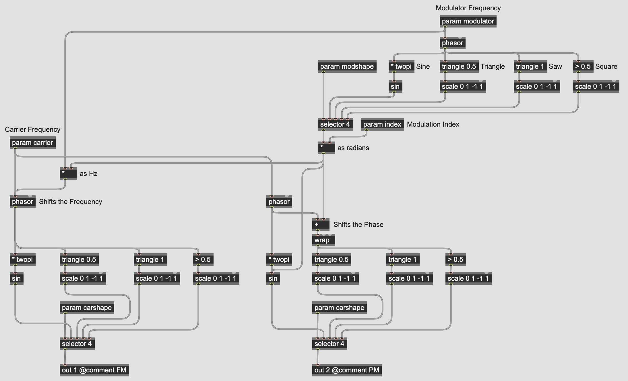
Thanks, everyone for the great feedback. I had to step away for a bit to deal with some life stuff, but want to get back to it. This is the gen~ patch that allows me to compare the outputs of FM and PM when using different basic waves as both modulator and/or carrier. I based the configuration for the PM of the sine wave on Graham's and Gregory's book and for the other wave types from the feedback offered here. Given that the phase control for the triangle, saw, and pulse waves uses values of 0 - 1, I used the wrap object to confine the modulation amount to that range. Does that look like I'm on the right track?

^looks good where the 'wrap' appears, but i'm realizing now on closer look that where you have it labelled, "as radians", is not actually outputting radians(-π to π, or 0 to 2π), so you could also switch that output from going directly into 'sin' to going into the '* twopi' just above it.
and then it should be good(but to be more mathematically exact, you'd want to 'scale' 0 to 2π into the range that is relevant before applying it as modulation, so it might be better to first make sure you have 'true radians' coming out of the top "Modulator Frequency" portion of the patch, and then use a 'scale -twopi twopi -1 1' op(or maybe just 'scale 0 twopi 0 1' depending on what you end up with), before going into the '+' op labelled "Shifts the Phase"... this creates a better 'mapping' of your modulator to the relevant control of your carrier(<-damn, there go my semantics again, but hopefully you feel me :D))
Thanks Raja! That configuration into the [sin] operator comes from one of the examples in "Generating Sound & Organizing Time." Having the modulation inserted after the [* twopi] operator causes the [sin] object to operate exactly the same as it does in the FM example when both operators are using sine waves. I'll keep working on it, and I REALLY appreciate everyone's suggestions and ideas!

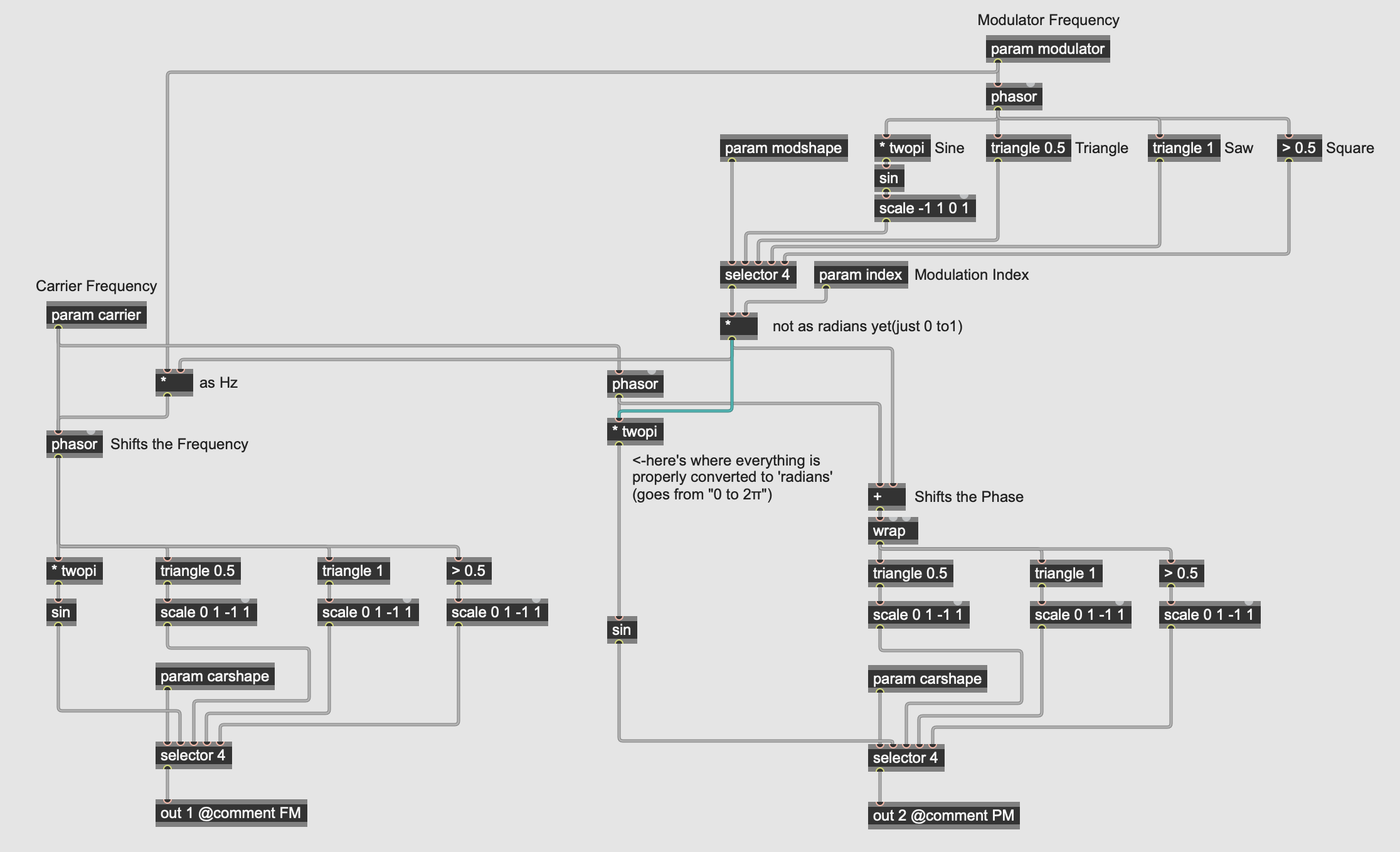
this is what i was thinking, given your patch:

here's just the gen~ patcher for that(but meant to be pasted/opened within a regular max patch):
...but i'm not sure if what i'm saying about proper 'mapping of radians' is correct/relevant here(if you're getting sonic control that you like, you should just go with it, i could be wrong).
[Edit: OH! That's interesting! The book doesn't label "as radians" properly(unless they meant loosely, "we're gonna take the range from '-1' to '1' and treat it bluntly 'as radians' by feeding it directly into 'sin' without any conversion whatsoever! yeehaw! 🤠 *guns firing in the air*"... then in that case, i see why they labelled it 'as radians' 😂... no wait! i'm the one firing my guns in the air willynilly: depending on how you multiply by the index, it could still scale nicely and be used 'as radians'... once again, i'm confused by semantics🫣]
[2ndEdit: but my problem with the original math involving the multiply-by-twopi is that if you take something that's going from -1 to 1, it can simply be multiplied by pi, whereas something going from 0 to 1 should be multiplied by twopi for the relevant mapping to radians(?)... if '-1 to 1' converts to '-2π to +2π' then i'd think that might be an unwanted doubling of frequency? (keeping in mind: -π to π is same as 0 to 2π in radians-based functions)]
Thanks, Raja! Yeah, I was wondering about the bipolar vs unipolar modulator thing. I need a bipolar modulator for the FM side. I was trying to use the same modulators for both FM and PM. Maybe I need to have both bi- and uni- outputs for the modulator oscillators. That was one of the advantages of connecting the modulator after the * twopi object; I could use the same modulator for both FM and PM with the sin objects, but was starting to realize that I needed to modify the output of the modulators into the non-sinusiodal PM oscillators. Wrapping it has the effect of making the other oscillators move a lot faster than the sine oscillator. That made me wonder if I need to scale it before it gets to the other oscillators since they expect to receive an input between 0 to 1 instead of (0 to 1) x ModIndex.
ya so many configurations(fun to try them all and enjoy all the happy accidental sounds along the way to what you like best).
was playing around with your PM patch, thinking of how i might apply the biquad filter algorithm to the phase-modulation path, here's what i came up with but it was a bit noisy so i added 'slide 8 8' before the input to clean it up a bit better:
just to help give some more ideas to try on phase-modulation(a feedback path can add a nice chaotic element; be careful with the 'b1' and 'b2' params, they can still cause the biquad to explode, in which case you can send 'reload' message to the gen~ patcher, restart dsp, reset all the params to what you like again, etc.).
It may seem surprising but in the phase modulation case, after multiplying a regular bipolar signal by the modulation index, you have a signal that is in radians. It surprised me when I was learning about FM and PM -- how does a bipolar (-1 to +1) modulator signal manage to produce a phase signal in radians? The simple answer is that the modulation index is itself measured in radians. So, bipolar modulator * radians index = radians phase shift. The modulation index is the ratio of output frequency deviation to modulator frequency. Explaining why this is in radians, and why 1.0 radians creates a full modulator swing (and not 2pi radians) is beyond a forum post... but trust me, your modulator is already in radians and doesn't need [* twopi]. So for example, if you wanted to phase modulate a waveform that uses unipolar phase (such as [phasor] or [sample]), you actually need to [/ twopi first, if you want the modulation index to behave the same way. It is weird.
The simple answer is that the modulation index is itself measured in radians. So, bipolar modulator * radians index = radians phase shift. The modulation index is the ratio of output frequency deviation to modulator frequency.
Ha! even when i think i've been mathematically precise, i fail 😂
i never would've known, but then again there is something intuitive to glean here from the fact that the index is a ratio(i should've considered the 'relatives' more carefully).
thank you!
Wow, I would have never guessed that. Thank you! You guys scare me! 😜
