How to address an LEDs strip APA106 MAX patch to Arduino

Hello!
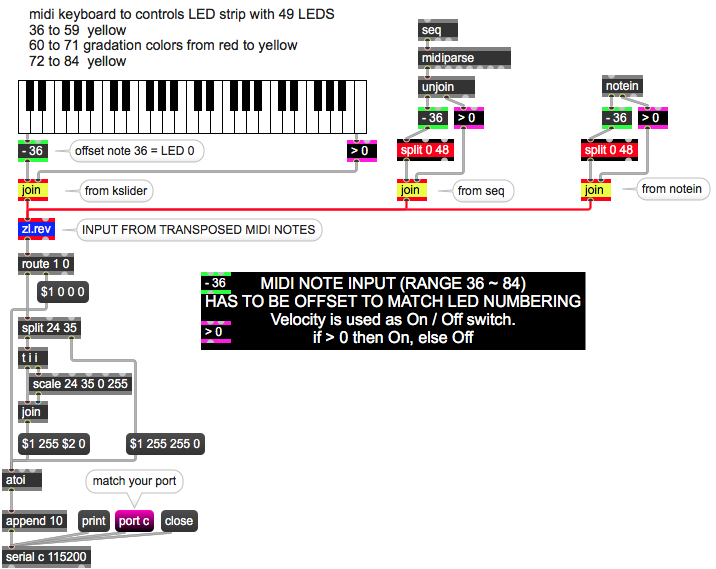
The patch is a midi keyboard to control a digital LED strip where there are 49 LEDS. From 36 to 59 (bass line) yellow, from 60 to 71 (gradation colors from red to yellow and the data is a MARKOV output) and from 72 to 84 just yellow again. Each LED lit up the color based on its corresponding MIDI note based on what note was pressed.
I would appreciate if any of you could help me with this issue.

Which issue are you actually facing? If you're wondering how to do what you want, you'll need to make a Max patch to format and send data over to your Arduino through the [serial] object, and make the Arduino code to receive, decode and interpret this data and drive the leds.
If you search for "LED strip" in the forum, you'll find several examples with Max patch and Arduino code. Seems like the APA106 LEDs are compatible with Adafruit's NeoPixels API, so you can add "NeoPixels" to your search to get more specific result.
The Arduino code is missing from your post.
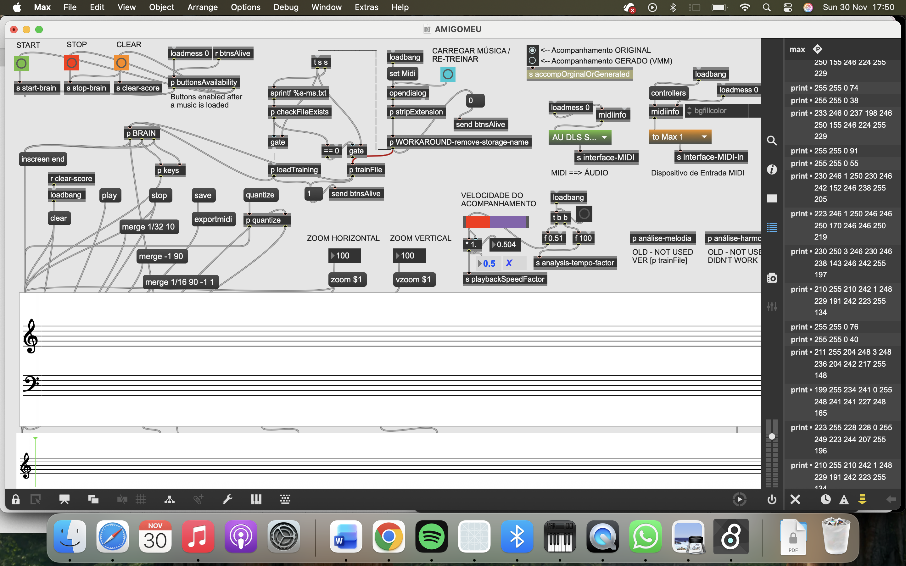
Also, no need to post your entire patch when you struggle with only a small part of it. I had to search for "serial" in the patch to know where to look at, but then I'm still clueless about how the data in the two [coll] objects is supposed to drive your led strip.
Many thanks TFL,
One Coll object reads the melody and the other the harmony. The file has to be in just one score. Thank you for the tip when sharing the patch.
#include "FastLED.h"
#include <Arduino.h>
#define LED_PIN 23
#define NUM_LEDS 49
#define BRIGHTNESS 32
#define LED_TYPE APA106
#define COLOR_ORDER GRB
CRGB leds[NUM_LEDS];
#define UPDATES_PER_SECOND 100
//CRGBPalette16 currentPalette;
TBlendType currentBlending;
//extern CRGBPalette16 myRedWhiteBluePalette;
//extern const TProgmemPalette16 myRedWhiteBluePalette_p PROGMEM;
void rainbow_wave(uint8_t thisSpeed, uint8_t deltaHue) { // The fill_rainbow call doesn't support brightness levels.
// uint8_t thisHue = beatsin8(thisSpeed,0,255); // A simple rainbow wave.
uint8_t thisHue = beat8(thisSpeed,255); // A simple rainbow march.
fill_rainbow(leds, NUM_LEDS, thisHue, deltaHue); // Use FastLED's fill_rainbow routine.
} // rainbow_wave()
void setup() {
Serial.begin(9600);
delay( 1000 ); // power-up safety delay
FastLED.addLeds<LED_TYPE, LED_PIN, COLOR_ORDER>(leds, NUM_LEDS).setCorrection( TypicalLEDStrip );
FastLED.setBrightness( BRIGHTNESS );
//currentPalette = RainbowColors_p;
currentBlending = LINEARBLEND;
//FastLED.clear();
//FastLED.show();
//Serial0.begin(115200);
//Serial0.println("The device started, now you can pair it with bluetooth!");
fill_solid(leds, NUM_LEDS, CRGB(255,0,0)); // fill red
FastLED.show();
delay(200);
fill_solid(leds, NUM_LEDS, CRGB(0,255,0)); // fill green
FastLED.show();
delay(200);
fill_solid(leds, NUM_LEDS, CRGB(0,0,255)); // fill blue
FastLED.show();
delay(200);
FastLED.clear();
FastLED.show();
}
int started = 0;
int dot=0, color=0;
void loop() {
if(!started){
rainbow_wave(10, 10); // Speed, delta hue values.
FastLED.show();
}
if (Serial.available()) {
started = 1;
// Read the incoming byte
byte incomingByte = Serial.read();
// Assign the byte to the appropriate color component of the current LED
if (color == 0) {
leds[dot].r = incomingByte;
} else if (color == 1) {
leds[dot].g = incomingByte;
} else { // color == 2
leds[dot].b = incomingByte;
}
color = (color + 1) % 3; // Move to the next color component
if(color == 0){ // If we just finished the blue component (color was 2 before the increment)
dot = (dot + 1) % NUM_LEDS; // Move to the next LED
}
FastLED.show();
}
// clear this led for the next time around the loop
//delay(20);
}

That should be much simpler.
You use predefined colors and no velocity based intensity.
So all you need is LED id and color number
for note on or black for note off.
2 bytes only
Remove delays from loop and increase
baud rate
That's all
I thank you for your kindness.
Maybe there is something in wrong with the max patch.
I changed the baud rate to 115200 and removed the delays in Arduino IDE.
That is what the console says:
print: 255 255 0 90
print: 255 255 0 54
status: write 13
status: write 12
the status write keep on repeating the same numbers (12, 13)
I had and still have no time to debug your patch.
You need only 1 serial object.
And you need a plan how to address the LEDs.
From what I understood from your initial post,
nothing in that arduino code and max patch
do that : light a LED depending on note number with specified color
and turn LED off when note gets turned off.
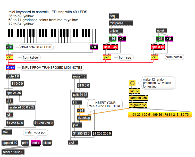
this is all you need to light that 49 LEDS from max.
replace kslider with output from seq
...
in Arduino parse LED number and 3 colors.
Genial! I can hardly wait to get home and give it a try.
Thank you so much!!!
Dear.
I tried patching the first patch you made with the output from the yellow keys and it does not work. Was it made for that output? For the output from the Markov I tried both with no success. I am sorry. I am confused.
That patch sends 4 values per midi note:
LED number (notes are offset to start from 0) and 3 RGB values.
If you know how to pass that to your LED strip, it should work.
all your LEDS are yellow , only 12 LEDS
note numbers 60 - 71 or LEDS 24 - 35 are gradation
from red (255 0 0) to yellow (255 255 0)
split object passes that range to scale which divides 0 255
to 12 values.
Is it not so obvious ?
I am sorry, I was counting 11 (and not 12) numbers between 25 and 34. that was driving me mad. I am truly sorry. Thank you for your patience.
Did you manage to parse the LED colors in arduino ?
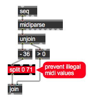
Is the number 0 (split 0 71) in your second patch right? Shouldn't be split 60 71? Once more I am confused. This second patch of yours is for the Markov output, right? The first patch is for the rest of the notes output, right?
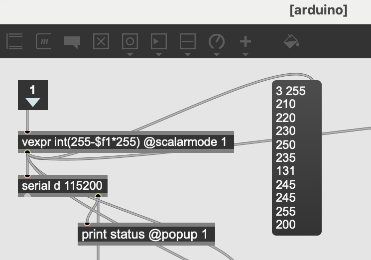
The arduino subpatch output from the original maxproj.
Could you also clarify this: "replace kslider with output from seq"
This is the console results when all the project is working.
Dear,
I am so grateful for your help, but there is something that does not make sense. You have sent me 2 patches, are those for connecting with the previous output from the original patch? Because the system is fully interconnected
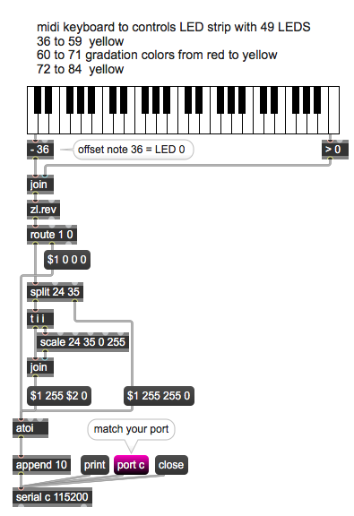
Patch 1 is with kslider, to show you how to send LED colors
to arduino.
The other one shows how to connect seq object instead,
because in your initial patch you were playing some midi file.
All you need is to properly input midi notes,
no matter if they come from seq playback
or from live played keyboard.
With proper I mean don't mess with multiple midi sources.
split object is meant for LED numbers, not midi notes.
you actually need only 0 ~ 48 , I left it higher
just for testing.
What is it that you don't understand ?
I thought you had made a patch to connect with my previous work, not only to present how to send the data to Arduino.
My doubt is within my max.proj and ask if the output data is correct to send to Arduino
The console results is in a picture above
Sorry, that is your problem, I have no time to go about that compliated patch.
Whatever you do in that patch, at the end product are 49 notes, On or Off.
That is what your initial post was about.
Simply remove everything that had to do with sending notes to arduino
and insert my patch instead.
here are 3 options shown :
Thank you. As soon as I get it working I'll make contact
but remember, you need note on and note off,
for both arduino and midi output.
Thank you. How is your patch going to work within the gradation colors that comes from the Markov chains. The colors change probabilities in each event, both from harmony and melody.
The patch you posted was not functioning at all.
there were send/receive objects without source or destination,
empty colls, no note off mesages and so on.
And you never really explained in simple words what exactly you want to do,
and how you create midi notes.
Untill that is clear, I can't help you.
I only took what is understandable from your initial post.
and that needs no markov chains, gradations or something else.
One Note - one LED.
If you want something else, than you have to explain it properly.
I had another look at your original patch
try this