
I don't fully understand the FM Bells gen~ example

Hello,
The picture is a colored version of the gen~ patcher from C74's FM Bells example.
I don't understand why the signal path is so different for the left and right modulators, and especially why the accum objects with blue and purple border in the picture do not get both the same information: one gets the frequency directly and the other the frequency multiplied by the c/m ratio.
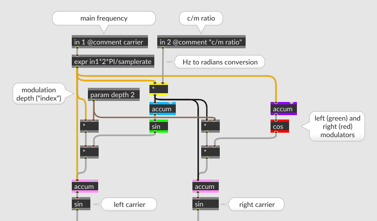

A comment in FMBells.gendsp says it is meant as an stereo FX.
The stereo dimension is created by a phase offset created by use of a sin modulator on one side and a cos modulator on the other side. But it doesn't explain why both accums don't get the same information, because they are upstream to the sin/cos.

Did you ever understand this? I don't even get the accum objects what are they for in this situation.
My guess is that the two different ways the L and R sides are connected somehow results in the same sound. But if that is the case I don't know why would someone do that in an educational example and not explain it further.

since cos "loops", accum might be the most effective way to do what it does here.
The accum is a way to add an increments to get a resulting phase position. The value at the output of the accumulator goes trough a kind of modulo operation at the input of the sin/cos therefore the sin/cos see a value evolving from 0. to 1. then going back to 0. (the same way the pong~ object functions in mode 1). The FM Bells is said to be frequency modulation but it's phase modulation actually (what Yamaha presented as FM synths were PM synths too).
so it is a kind of a small "homemade" sine oscillator? accum goes potentially into infinity and drives the cos.
it makes me feel kind of uneasy to know the accum signal goes god knows how large , it doesn't affect the CPU or something?
It can grow to very large numbers indeed. But current computers with 64bit resolution can handle this. Still I'd be curious to know how long one could let the accumulators run before overflow.
ok thanks for the detailed info
Someone knows who programmed this patcher?
not only that in 64 bit enviroments you can run accumulation of small floating/fixed point numbers for hundreds of hours in practice, that gen object it might eventually even be able to restart itself when it reaches the end.
i doubt that MSP´s phasor~ works like that internally, but even that would be possible.
so then why cos? (which is far more expensive than using wavetables?) probably because it is more exact. using a wavetable requires interpolation, and that is always a loss of precision.
Just for the fun, I've let an accumulator (+=~) run during the whole night at 44.1kHz and it has still not reached overflow.
Also, I think the cos question was about why cos versus sin. It's simply because sine and cosine functions are similar but there is a phase offset of a quarter of a cycle (that is 90 degrees or, in radians, π/2) between them. So using a sine on one side and a cosine on the other side could produce the same frequency on each channel but with some decorrelation and so this creates some stereo width. However the question of my original post remains.
how do you input inharmonic c/m ratios into this gen patcher? as float?
Indeed, but I suppose a signal would function too.
somehow i feel it should be 2 independent parameters. :)
Which ones?
dividend and divisor? "5:7" reads much better than "0.7142"
if there is only a "ratio" input, it could as well men you have to input the n for 1:n.
I don't agree because usually when the ratio is an integer the sound has harmonics whereas when it has digits after the dot the sound has inharmonics. Simple.
it is only a matter of representation (to the user). 5 : 7 will sound exactly the same as 0.7124 : 1., and both are considered "inharmonic" ratios. (and it will create inharmonic as well as harmonics sidebands)
but if you enter two numbers - or a fractional number - you can see what they are about. if you have to enter the result you have no idea where you are at. i tend to put the "normalisation" to base 1 into the signal algo and give the user 2 independent parameters.
Tous les goûts sont dans la nature...
haha, nah, it´s math: rational numbers are made of whole numbers, not floating point values.
many synths show fm or rm ratios of "1 : 2,75" to the user, but that just doesnt make sense.
1 : 2,75 is eventually 4 : 11, it is always ints. because otherwise it won´t be a rational number.
but i quit now. your original questions remains interesting enough already (and unsolved.)