
Matrix~ advise on incoroprating

Hi,
I'm designing an audio-visual installation/ performance and have made a patch which uses 16 inputs to control filters (granulator, reverb and delay). I'm a newbie and have to a bit confused and need a bit of help figuring out audio inputs (where they are patched to) but also I need help with mixing the audio live as there will potentially be 4 different audio coming in, either recorded directly into the patch or direct just a constant direct feed.
Re: mixing - I know I need to use the matrix~ object but don't know where it goes in the patch. before or after filters.
Atm it's been arranged (for testing) and I've used an audio file to indicate where I want the separate audio to come in but havent included the two other inouts. I don't think I need as many dacs as I have. Everything needs organising better/ simplifying. Please help?!
Ahhh... is this better?
Thanks for the reply. And I've taken on board your comments. Appreciated.
I've just updated my patch although cant seem to scale roomsize for some reason?
I will have 3 or 4 analogue inputs (just patched these in - have I done this right though?)
1 comes in is recorded and looped - goes to Reverb
2 comes in is recorded goes to granulator
3 direct input and will go through a filter (haven't done this yet)
I do want to add post fader send to reverb, yes.
At the moment I've put them through 2 matrix~ for stereo and the matrixctrl~ so I can mix, but might if there's a better way of doing this I'd appreciate feedback as I only really want to mixing the audio together and not worry about bringing in left and right two (if that makes sense?)

matrix~ has simple logic.
you tell it to send input instance to output instance with set gain.
0 0 1 - means input 0 goes to output 0 with gain 1.
Matrix makes sense in some cases cause it is simple, has ramp time option,etc.
But in some cases one is better off using separate sliders.
sorry, but I get nervous when looking at that big patches with so many waisted space and objects.
here is your initial patch with few changes
before doing any routing you need to define how do you start/stop recording, from which source etc
P.S.
that reverb (gigaverb ) is also available as external
Ok - done this so far -
There will be 3 inputs. Hoping I can use external midi to start/ stop etc
Havent included Matrix yet. sliders to mix/ fade in but I have the basics in previous patch that I hope I can incorporate and again use external midi to control these.
Thank you so much. Really helping me organise the patches. I think I'm slowly getting there. I know this is probably basic stuff and I've found it complicated but this is after 3 weeks.
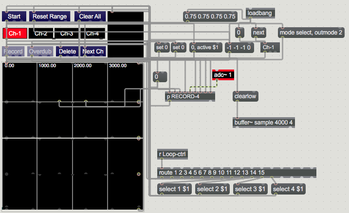
here is 4 channel looper, it has overdub , but one can remove it if you want.
it uses fixed 4000 ms length, and buffer named sample.
so take care to remove same buffer name from other patches.
see if it fits to what you need.
one can select a channel or step through, select loop range using top waveform.
We can assign midi controls as you wish later.
instead of 4 mute or solo buttons there is 4 channel multislider.
sorry, yes I will assign notes. I think I know how to do this as I have a had a play around with it using the my Novation controller.
Yes all LDRs tested. and working well.
Just to let you know I sorted the mixer out. It might not be completely the correct way of mixing multiple audio signals in Max/MSP but this is how I've done it after head scratching :))) It means I cant have a reverb after the mix though.
sweetest pie is self baked one,
even if someone else can pack it nicer ...
I prefer other objects, but you can also look into live.gain~
it is stereo allready and has level meters built in .
Just post if you need any further help.
I detected few connection mistakes in your last patch but maybe you sorted that
allready.
I looked at arduino code ...
It sends string of 16 values no matter if they change or not.
And you have no control of real available range.
If you want to experiment - improve that
let me know. But maybe you have other priorities
Your help has been incredible. I appreciate it so much. I was lost before
Re: arduino - I would like to look more closely at this. I was thinking I needed to tweak the range to make it more manageable otherwise they're just going to be everywhere and it will be a cacophony.
I detected few connection mistakes in your last patch but maybe you sorted that
already.
I think I have yes but if you could maybe annotate where these are so I could have look again and see if I got it right. I may have missed something. Its been a steep learning curve and I still have a long way to go but feel much better about Max. I've attached my patch again if you have the time.
And also I'm more than happy to look at alternatives to gain/ live.gain. This all all really positive stuff.
I am out of the house for a while.
It is good to have updated patch from you.
I will have a look later.
No problem. Thank you. Let me know what you think.
back again ...
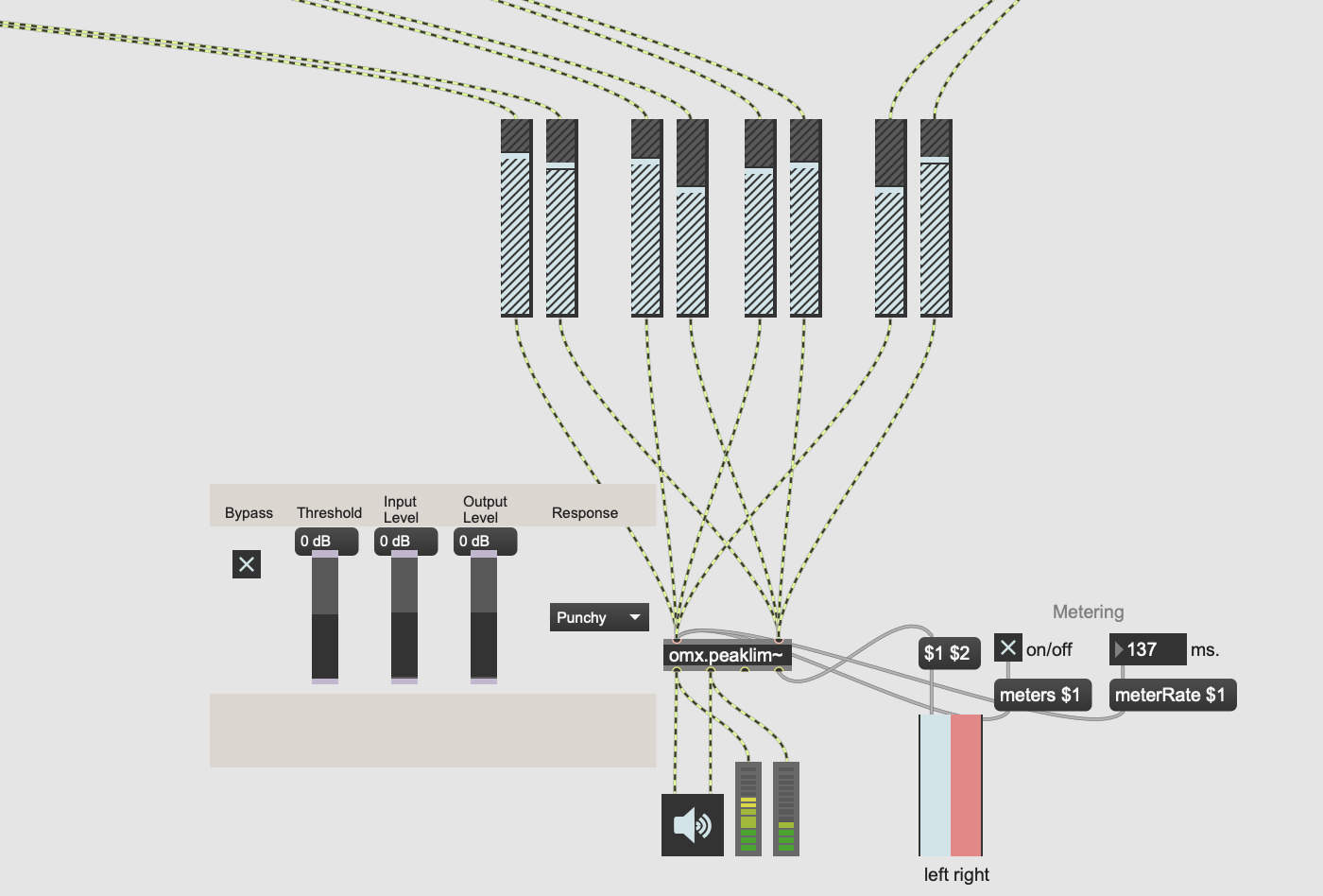
connections to omx.peaklimiter are wrong...
you should connect stereo output of all live.gain sliders to limiter's stereo input.
check scalers for reverb ... 300 second reverb ???
0.2 - 20 should be more than enough ...
I have again made some work on the patch, in first place packing stuff
into sub patchers to have better GUI.
Reverbs now have have dry/wet mix, so that you can pass dry signal through if you want.
I asked about that a while ago, but you did not decide about dry signal.
added storage for parameters so far.
Thank you so much!!! I ll look at it properly tomorrow. Can’t believe how much you’ve helped me.
This is amazing!
I'll play around with it and check:
connections to omx.peaklimiter
scalers for reverb .
Honestly don't know how much I appreciate this it's been a huge help. I've learnt a great deal from you.
I'm working on the installation from next week and the following few weeks (I took a few days off this week - literally maxed out! :))) so I'll let you know how it all goes.
Kindest kindest regards 🙏🏼
you might need help with LDR's as well.
I had no time to really explain all in detail,
but you will need to adjust resistor that forms voltage divider,
depending on type and specs of LDRs that you use.
That 10 kohm shown in most tutorials is a bullshit.
You need to know dark ~ bright light resistance of your LDRs
which differs a lot from type to type, as well as check with what you deal
in installation, then adjust that resistor, and maybe arduino reference voltage.
Only that way one gets most of LDR measurement.
you need only 1 resistor at A0 input on arduino.
All LDRs can be wired directly to multiplexer inputs and +V
Could you post your LDR type and arduino board that you use ?
This is really interesting.
ATM I'm using 10ohm on each LDR going into a CD74HC4067 16-CH Analogue Digital MUX Multiplexer
I'm using the Arduino uno r3 but switching this out during installation for the R4 wifi board
I was thinking I'd needed play around with the resistance but ATM its all on a bread board and I haven't protyped it just yet.
I have A0 going into sig on the muliplexer.
LDR can have for example 2 MOhm at total dark and 10Kohm at full light,
like when you place bright LED on top of it.
or 400Kohm / 2 Kohm
etc
There are many different types.
10 Ohm ? how is that going to work ?
LDR resistance together with resistor forms voltage divider.
Or dynamic resistance pot if you want so.
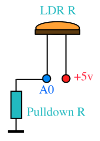
if resistor is 100K and LDR sits at 10 K then you have
5v /110 * 100 = 4.54 v or A0 value 930
in case of 10k resistor it would be 2.5 v or A0 value 512
......
You should measure your LDR's and make simple resistance test
in front of that projector.
One can isolate that many LDRs in room
by placing them into black tubes, to focus light detection as much as possible.
Even filler, or ballpoint pen tube and similar can do.
you will find here info about setting analog reference
for different boards.
that shifts voltage range in order to get full scale sensor readout if sensors can't reach full voltage range.
........
There are other things waiting to be done, like midi control,
You wanted to add another scaler/multislider for filter ?
just post when you need further help.
hey. how you doing.
I took a bit of time off.
Just strating to set up installation and mess about with different film projections.
All good except i've come back to the patch and theres no adc~1
seems to be just input through mac microphone. Am I missing something?
adc~ 1 is inside of loop recording bpatcher.
thanks, I thought that but I cant seem to access it. need to select the input
Also - do you think I should add zl stream, zl median, or slide to smooth out incoming data?
I'm using 100k ohm - works well. Readings range from very low to 1000 so far with projector so tests have gone well so far. Just built a big installation and playing around with film and optical sound input etc. all looking good but just fine tuning now. Swapping out two LDR's but rest work great.
I've had a huge amount of stuff on so had to leave this to one side for a bit.
Just accessed bpatcher btw - sorry
You should first look what you send from Arduino.
I mean in what interval, and if you send only if values changed.
your send 1 list with all LDRs so even if only 1 detects changes to light, you send full list.
How would you smooth that at input ?
One would have to work on outputs in scaler subpatch.
insert change 0. to remove repetitions, and if you still have too fast data
then you can try zl stuff
now it is probably too late to rewrite Arduino Code
I've just re-read one of your previous messages
I looked at arduino code ...
It sends string of 16 values no matter if they change or not.
And you have no control of real available range.
If you want to experiment - improve that
let me know.
How can can I change this? is it worth it do you think?
Are you willing to rewrite code short before installation ?
I don't know what I looked at really, you did not post arduino code,
it is only receiving full string that tell's one what is at input.
To do any better, you would need to send individual
LDR values using prepended ID, so that you can route that in max.
More you smooth a list, less responsive is your system.
It all depends how precise you want all to work.
If you have good enough separation between 16 LDR readings,
and enough range to use as control, then you can leave it as is.
And try to ease a bit output of end controls,
in order not to produce too much strain without noticeable effect.
To your question - is it worth ?
sure it is even if only for learning purpose,
but main thing is that you get your installation work in first place.
here is code for you to try :
unsigned long LDR[16] = {0,0,0,0,0,0,0,0,0,0,0,0,0,0,0,0};
unsigned long exLDR[16] = {0,0,0,0,0,0,0,0,0,0,0,0,0,0,0,0};
int THRESHOLD = 5; // threshold for "Value Changed" recognition, change as needed
void setup(){analogReference(DEFAULT);
// analogReference(INTERNAL); analogReference(EXTERNAL);
pinMode(2, OUTPUT); pinMode(3, OUTPUT); pinMode(4, OUTPUT); pinMode(5, OUTPUT); Serial.begin(9600);
}
void loop(){for (int i = 0; i < 16; i++)
{digitalWrite(2,i&0x01); digitalWrite(3,i&0x02); digitalWrite(4,i&0x04); digitalWrite(5,i&0x08);
LDR[i] = analogRead(A0); if(abs(LDR[i] - exLDR[i]) > THRESHOLD)
{Serial.print(i); Serial.print(" ");
Serial.println(LDR[i], DEC); exLDR[i] = LDR[i]; delay(10);}
}}
..............
commented out :
// analogReference(INTERNAL); analogReference(EXTERNAL);
are ther in case you need to adjust it, but as you seem to get enough
at input you can leave it out.
.......
multiplexer pins 2 3 4 5, A0 = input pin
16 inputs get read in a loop and compared with previous reading.
If difference exceeds threshold ( set to 5) output that channel.
you can adjust threshold value to match youtr LDR performance.
IDs range from 0 ~15.
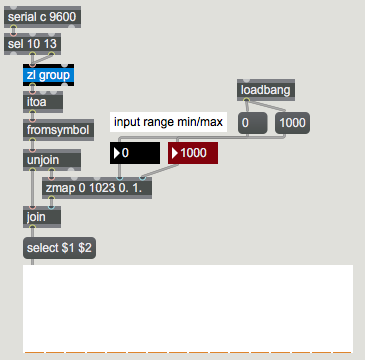
In Max :
appreciated. thanks so much i'll try yours out.
I ammeneded my code this morning to this to make it smoother but will try yours too:
// CD74HC4067 pins
const int pinA = 5; // S0
const int pinB = 4; // S1
const int pinC = 3; // S2
const int pinD = 2; // S3
const int analogOutputPin = A0; // Connect to SIG pin of CD74HC4067
unsigned long previousMillis = 0;
const long interval = 10; // Read interval in milliseconds
int previousValues[16] = {0}; // Array to store previous sensor values
const int threshold = 10; // Threshold for detecting significant change
const int numReadings = 10; // Number of readings to average
void setup() {
// Set multiplexer control pins as outputs
pinMode(pinA, OUTPUT);
pinMode(pinB, OUTPUT);
pinMode(pinC, OUTPUT);
pinMode(pinD, OUTPUT);
// Initialize serial communication at 9600 bits per second
Serial.begin(9600);
}
void loop() {
unsigned long currentMillis = millis();
if (currentMillis - previousMillis >= interval) {
previousMillis = currentMillis;
bool dataChanged = false;
// Read values from each LDR
int sensorValues[16];
for (int channel = 0; channel < 16; channel++) {
sensorValues[channel] = averageReadings(channel);
// Check if the sensor value has changed significantly
if (abs(sensorValues[channel] - previousValues[channel]) > threshold) {
dataChanged = true;
}
// Update previous values array
previousValues[channel] = sensorValues[channel];
}
// Send data if any value has changed significantly
if (dataChanged) {
for (int channel = 0; channel < 16; channel++) {
Serial.print(sensorValues[channel]);
// Print a space after each value except the last one
if (channel < 15) {
Serial.print(" ");
}
}
Serial.println();
}
}
}
int averageReadings(int channel) {
int sum = 0;
for (int i = 0; i < numReadings; i++) {
selectChannel(channel);
delay(5); // Small delay to allow the channel to settle
sum += analogRead(analogOutputPin);
}
return sum / numReadings;
}
void selectChannel(int channel) {
digitalWrite(pinA, channel & 1);
digitalWrite(pinB, (channel >> 1) & 1);
digitalWrite(pinC, (channel >> 2) & 1);
digitalWrite(pinD, (channel >> 3) & 1);
}
TBH i think i'm overthinking. I think everything is ok -
the sensors work as they should (I think). I think youre right about smoothing things out too much. It's actually quite a simple circuit and I think they key is to know when to stop.
The patch is great thanks to you.
I need to fine tune the film material and installation.
I'm still learning and this has been intense but great. Thanks for all your help.
LDRs are slow themself.
one does not need to average the readings I think.
I would read sensors as fast as possible, but send only ones that
changed > threshold, as in my code.
Then you can deal with result in max.
I don't have that book,
and also I am not really using gen~
OK so - I'm very sorry but may need a bit more help.
Everything is great apart from the fact that the projector i'm using runs at24fps (flicker rate of 48) which means that the reading fluctate quite a bit. I've tried adding an 'interval' and calculating the flicker to be 20-30ms but its not really helping.
do I need a capicitor or can I add something in Max or is there another way around this?
Your LDRs have specified rise & fall times. I asked you to post specs or at least model of LDR you use, never got an answer.
24 FPS (41.66 ms) in worst case is toggling black and white screen which is slower then fast LDR
having average 30 ms rise/fall time, again - it depends on LDR type.
If you use one single pull down resistor on Analog Input, there is no way to insert
fast charge / slow discharge RC combination.
Because it would affect all 16 LDRs.
So you either do it 16 times on each input,
or then try something in software, like slide.
I'm using LDR Bojack GL5539
100k ohm
I've played around with code and its much better.
Will try maybe change out resistor as the reading with my new projector bulb (otherone blew last week) and averaging 500 rather than full 0 - 1023.
Thanks again. last couple of weeks panic
Heres code.
// Define the pins for the multiplexer control
const int pinA = 5; // S0
const int pinB = 4; // S1
const int pinC = 3; // S2
const int pinD = 2; // S3
const int analogOutputPin = A0; // Connect to SIG pin of CD74HC4067
unsigned long LDR[16] = {0}; // Array to store current LDR readings
unsigned long exLDR[16] = {0}; // Array to store previous LDR readings
int THRESHOLD = 2; // Threshold for "Value Changed" recognition
unsigned long delayTime = 5; // Shorter delay time in milliseconds for real-time responsiveness_maybe remove this if Max isnt responsive
int numReadings = 5; // Number of readings for averaging (higher for more stability)
void setup() {
// Set multiplexer control pins as outputs
pinMode(pinA, OUTPUT);
pinMode(pinB, OUTPUT);
pinMode(pinC, OUTPUT);
pinMode(pinD, OUTPUT);
// Initialize serial communication
Serial.begin(9600);
}
void loop() {
String output = ""; // String to accumulate the output
for (int i = 0; i < 16; i++) {
// Select the channel
selectChannel(i);
// Read the sensor value multiple times and average the results
unsigned long total = 0;
for (int j = 0; j < numReadings; j++) {
total += analogRead(analogOutputPin);
delay(4); // Small delay between readings to stabilize
}
LDR[i] = total / numReadings;
// Add the value to the output string
output += String(LDR[i], DEC) + " ";
}
// Print the accumulated output string
Serial.println(output);
// Delay to slow down the serial monitor output slightly
delay(delayTime);
}
// Function to select the multiplexer channel
void selectChannel(int channel) {
digitalWrite(pinA, channel & 0x01);
digitalWrite(pinB, channel & 0x02);
digitalWrite(pinC, channel & 0x04);
digitalWrite(pinD, channel & 0x08);
}
I know GL5539
bright light can set it at 100KOhm or less, total dark up to 5MOhm.
rise time 20ms, fall time 30 ms, es expected.
You should measure resistance which your projector creates,
get min/max values.
From that one can adjutst resistor value for best result.
If you used 100K resistor , even brightest light can not give you more than
half of analog input range.
You either increase pulldown resistor, adjust analog reference voltage, or scale it in software.
I mentioned all that long time ago.
Thank you.
Yes I remember now, you mentioned it a long time ago. I'm sorry. Theres been a lot to take in and so many different elements to the project.
I've scaled in zmap and all good. I dont want to chnage ldr's or resistors because the net bulb/ projector could well be brighter so flexibility to change in max is good.
Thank you.
if you need to tame to fast rise or fall of readings check slide object.
OK cool. Would I put this after zmap?
I would place it at the source at input, before any scaling or other manipulation of input.
Hey,
Everything is great - cant thank you enough.
I have one very last question and it's just about mapping to midi - it's all mapped but my problem is that Novation launch control XL works but wont light up. I've tried sorting this out and search forums and realise it's something in the patch I need to add but cant seem to do it. It's not ha importnat but would be better for performance if this worked. Please could you advise?
I have no idea what novation unit needs to have lights controlled,
but if you provide enough infos, I'd be very glad to help you out.
I need all midi flow infos that you use in your patch.
And ---- I never use midi mappings.
I use direct CC or notes... whatever, assigned to controls I use.
So can't help you when it comes to that mappings stuff.