
Question about a patch in Gen~ book Generating Sound & Organizing Time

hello guys,i am trying to learn gen~ and cant understand this patch in the book:
From what i can understand,this is a sync-related patch that can send out sync position depended on what we the sync value we input,there are three parts of this patch,I'll try my best to write down what i can get from this patch,correct me if i said anything wrong:
Let's say ratio is 8
the result of right part give us the current position of the phasor,if there is no trigger detected this value will be out put and wrapped within 1,the speed of this phase is 1/8 of the original,which is 8 times slower than the original phasor
the result of left is somekind of a trigger detect function which can detect whether there is a trigger or not
what confuse me is the middle part,it use the original phase * 1/ratio(which is 1/8 in our case),get a value that maximum is 1/8 of the original phase(kind like a offset,tell us how far our phase went within 1/8 step),then
subtract this phase offset,round it @ trunc mode by 1/8,which will give us a value behind our current position,but synced with our ratio,then add offset back
I mean,from my personal experience about synthesizer,a sync function is suppose to give us a position that out next sync should be send out,but no matter how i checked through this patch,it will only give us a position behind our current position,not ahead of it,so what is the purpose of knowing a position already passed and what we really need is a position ahead of the current one?
so i must understand something wrong,I 've been stuck here for a day,somebody please help me……thanks a lot

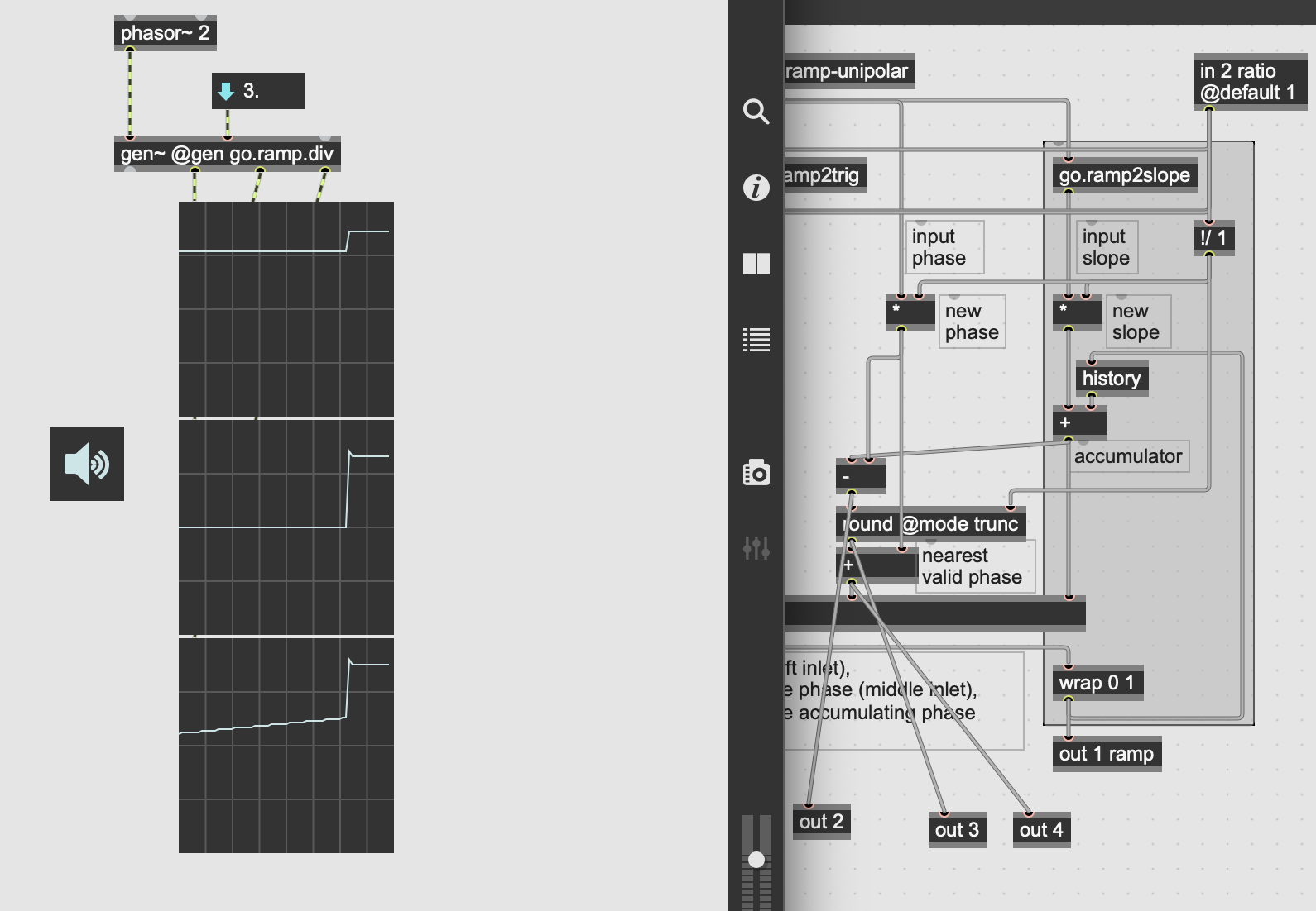
it can help to create separate outlets within the gen~ patches studies to send to scope~ object outside, there, with multiple scope~s lined up against each other (top-to-bottom, or overlayed with transparency and different coloring, whatever you prefer), you can see the differences between what you get in one inlet of the 'switch', as opposed to the other, both at the same time in scope~s lined up against each other to see the how the changes are also synchronized.
this can help you understand the math visually(perhaps even more instinctually)... otherwise, this is very difficult to describe in words.
but here are a few further notes i can think of, just in case it can help:
-yes, you are correct with ratio of '8', it is "8 times slower than the original phasor"
-the result of left is a trigger impulse, but it occurs whenever you change the ratio drastically(and also, this behavior only while 'autosync' is set to 1, otherwise, you can turn autosync off('0') and send a reset trigger by inlet 3)
-for your confusion over the middle-portion of the patch, it's hard to explain in words mathematically better than in the book:
"in this patch the trio of -, round, and + operators make it jump to whichever viable sync value is nearest"
...so the book is saying: sometimes ahead(or rather, right on time), sometimes behind -> see how it integrates the history from the output right around where it's labelled 'accumulator', it then subtracts the new phase from that.
after that, truncation quantizes it down to a specific boundary, but then there is addition after that as well which should, at times, bring it back up to the most current sync point(instead of the one behind)
i could be wrong(sometimes i'm inexact in my measurements because i use scope~s to get a bird's-eye/intuitive view, and then try to 'sculpt' signals by memory of what i see there, over time, i've gained some intuitive thinking about which algorithms might help me apply a shape i want to sculpt from the signal given - this is one little form of digital-signal-processing through visually induced intuition - try scoping after the '-', then also after the 'round', and then also after the '+' and comparing all three of those outputs together),
this screenshot probably adds more confusion than it solves...
...but hope it can still help get you further in the right direction to the answers you seek 🌻
thanks!I will try to chew over these valuable info~
I think I can explain my confusion better now:
1 Based on if what i said earlier is true,the middle part subtract this offset,use round @mode trunk then add this offset back
2 The Problem is,mode trunk of round is basically acting like trunk object right?no matter how far float goes above an int it will trunk the float part,like 3.8 = 3 after this object,so the result will never ahead of what our phasor is really at right now,and if the result's Position is behind,there is no meaning to sync right?because from what i can understand now,sync is something must happen after we do the “sync move” ,like if this patch detect a move happened at 3.8,and our sync unit is like 0.2,the patch should give us 4 as the sync Position but now it can only give us 3.2,how to “sync”from a Position that is already passed?
there is no meaning to sync right?
there are quantization boundaries which you sync to, doesn't matter which one, the rhythm will be synchronized. there is 'meaning' to sync(but the word 'meaning' is also subjective: they have "meaning" that counts towards the proper perception of an accurately iterated rhythmic boundary.. you have to put it into practice to understand fully).
I think I can explain my confusion better now
...i think, you've only confused me more by introducing more of your own subjective terms like 'sync unit' and "sync move"(what are these terms?)...
simplest answer i can give:
if you want to sync to the 4 instead of the 3, using [round @trunc], you can, you just add "0.5" to everything in order for it to become early... but if you try the patch in practice, you'll see there's no 3 or 4, there's just 0 through 1(not including 1)... and i notice you've labelled "0.2" a 'sync unit', but that doesn't make sense to me... is '0.2' a sync unit of a quarter-note? eighth-note? or maybe you meant the difference between 3.8 and 4? that's not a 'unit', but just the amount you need to shift up to get to...
but then again, to get to what exactly?
in the case of phasor-based clocks, you shift back up to... "1"?
but no, a phasor wraps between 0 and 1,
so all you can work with, is the next 0. even in your 'personal experience' with synthesizers, this is how the illusion of synchronization works under-the-hood: there is no next '1' it wraps back down to '0', then the cycle repeats and any values that were sampled-and-held are released.
if you switch ratio from (the equivalent of) 'quarter-note' to 'eighth-note', when do you expect the next eighth-note to occur? at the soonest possible eighth-note boundary that happens next(no need to go back into the past and start from the previous quantization boundary... even if one could).
if you put the patch into practice, you'll understand it better(and you can try removing @mode trunc from 'round' to see if that's what you expect, you can even leave it at 'trunc' mode, but add '0.5' to everything right before that, it will then truncate to the upper integer, everytime the phase is above 0.5... see if that does what you expect better).
putting it into words(and only looking at the book, trying to understand the patch as is from the pic) will not help you see why 'there is plenty of "meaning" to sync' according to how its done in this patch :)
i'll leave this for others to explain further(i feel i'm just getting more confused as to your confusion😅). you seem to understand most of it, it's just a matter of not thinking so much about it and just using it, then the experience of how it works will make sense, best of luck 🍻
thanks for your answer,i will try to do understand your meaning by doing more experiments~
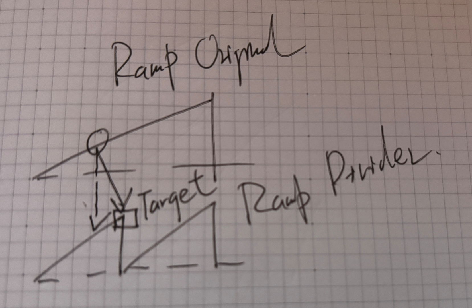
I think an image is a better way to show what i mean:
1 basically what we are doing here is to create a clock divider right?using the ramp below
2 my point is,the “real” sync trigger(target below)should always happen after the position that our divider detect there is a “sync” attempt(round point above),which is our current position
So,if what i said here is right,i cant understand how the middle part,using the position we are right now minus the new phase,then trunc the result of it(which will let us to the nearest multiple of 1/ratio below our current result),then add the new phase back,could give us a sync position that is ahead of our current position,cause trunc is always make the number smaller

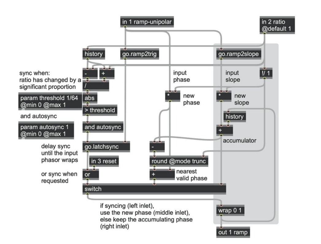
What I can do is try to talk through the patch in a bit more detail in the hope that this clarifies something for anyone reading this thread. Then I'll try to answer the specific original question at the end.
---
So the basic idea here is to take one phasor and generate a new phasor of a different but related frequency (as determined by the ratio input in2). If ratio is > 1, then the output phasor will be slower than the input phasor (like a clock divider), and vice versa if the ratio is < 1 (like a clock multiplier).
Here's how the main part of this works:
determine what the slope is (the rate of change as frequency per sample) via
go.ramp2slopedivide that slope by the ratio to get a new rate of change (frequency for the output phasor) -- this is what the
!/ 1and*ops are doing in the grey box at the right side of the patch.run this slope through an accumulator to generate the new phasor, via the
historyand+andwrap 0 1ops in the grey box.
The rest of the patch is all about syncing the output phasor, which requires two things:
A) knowing when to sync, and
B) knowing what value the output phasor should jump to when a sync request happens
The left hand side of the patch is all about (A).
the first part (the
-,+,\,absand> threshold) creates a sync request trigger if the ratio suddenly changes by a large proportion. So, if you slowly change the ratio, it doesn't try to resync, but if you make a sudden change to the ratio, it will try to resync. That makes sense for many situations. This section can be disabled by settingparam autosyncto zero.the next part (`go.latchsync`) delays this request until the input phasor next wraps around (as detected by
go.ramp2trig), so that the sync happens "on the beat".the last part lets you force a sync at any time via
in 3 reset, combining both triggers via anoroperator.
The sync trigger is routed to the switch, to interrupt the normal flow of the phasor (accum, + , wrap 0 1) and force a phase change via the switch's middle inlet.
OK, so now the middle part of the patch is all about (B): figuring out what phase to jump to when a sync happens.
Here we also have two jobs:
find out what the nearest valid sync point is
make it sub-sample accurate
Let's start with (2) -- and why it is needed: When you sync an analogue saw tooth wave you'd just set the phase value to zero and let it accumulate from there. But in a digital realm we shouldn't have sync reset a phasor to zero, because for strictly accurate timing, the sync event would actually happen somewhere between one sample frame and the next, and both input and follower phasors should have reset and already started accumulating a partial sample by the end of the sample frame in which a sync occurred.
If you looked at the value of the input phasor when a sync happens, it won't be zero, it will be slightly more than zero. E.g. if the input phasor slope was 0.1, and the sync event happened exactly half way between one sample and the next, then the input phasor value will be 0.1*0.5 = 0.05.
Similarly our output phasor should be nonzero. The actual phase value it needs depends on the ratio between the two phasors, which is why we have the * commented with "new phase" in the middle of the patch. This is simply computing what the output phase should be after a sync reset. It is almost always going to be a small number.
OK now for (1). First, why is this needed? Consider the case where your ratio is 4, which means the output phasor is 4x slower than the input phasor. In that case, there are actually 4 places where the output phasor could sync to that would still be "on the beat" -- that is, when the input phasor value is 0, the output phasor could be 0, 0.25, 0.5, or 0.75. The patch so far would always select "0", which is not necessarily what you want.
So the last part of the patch, with the round operator, is there to make the output phasor jump to whichever potential sync point is nearest, which is not necessarily 0.
First, we take our previous output phase (the point commented "accumulator"), and subtracts the new subsample phase, to find out what the phase actually was when the sync happened.
Then we round this value to the nearest substep (e.g. 0, 0.25, 0.5 or 0.75 in the case of ratio=4), via the
roundoperator.Finally the
+operator adds back the partial phase to make it subsample accurate again, per (2).
---------------
OK so that's the whole patch explained, hopefully!
Your question was about why we used @mode trunc on the round operator. The @mode trunc attribute just means that the round operator always rounds down, so e.g. with ratio=4, if the phase was 0.49, it would round down to 0.25. If we didn't have @mode trunc, 0.49 would round to the nearest, which is 0.5.
I think it's a totally valid question, and maybe you might prefer the behaviour without @mode trunc. I'd suggest trying it out in different use cases and seeing what works for you best. Personally I think there are valid arguments for both -- the idea of skipping ahead to the nearest may make more sense in some cases, whereas the idea of only ever jumping backward may be more intuitive in others.
You could even make it a variable option: if you want to jump to nearest, insert 0.5*slope right before the round and subtract 0.5*slope right after it. That 0.5 multiplier could be dependent on the value of a param, so you can selectively enable/disable it (or even control its sensitivity!)
We didn't do this in the book because this patch is already complicated enough to understand!!
wow!thank you, Graham! I think after I read your thorough explanation I can understand more of it, hope the explanation is right:
1 When the sync trigger is detected and sent out, the right part of this patch, the function of which is creating our new phasor by accumulating slope, will be like “new slope( slower than before if the ratio is bigger than 1) + old phase Position(created by history object)”
2 Then, we subtract the new phase, which is something like “after ratio changed, how long our new phasor moved from 0” to get the exact position of where the sync event happened
3 We round this Position to the nearest “sync unit” possible, to make sure that no matter when we try to sync manually, it will be synced to the nearest “sync unit”
4 then the last part, why add the new phase back, is a bit hard to understand, you said in the digital world for strict time accuracy, sync should happen between samples, but gen~ is operating per sample,so does it mean these 2 phasor cant be synced at point 0 or Phase 0 no matter what?so when the sync trigger start it actually already moved a little from 0?that's why we add this “sub-sample accuracy” value back?
If what I said here is true,this is totally new to me cause I always assume there is a “0” point when synced
And the more I understand this patch, the more questions I have……The Left part of this patch is like a sync detector right? But it will only function when the Original phasor sends a trigger(when wrapped), does that mean if I make a sync attempt within the one cycle of the Original phasor,this sync attempt will be “latched” until next wrap point?
So if our Original phasor is very slow, and we use this divider as a multiplier,we change the ratio within one cycle multiple times, does that mean all those changes will be unsynced?cas the right inlet of the last switch will send out the new phasor ramp Immediately whenever the ratio changed
Another question is, what is the “sync” mean in this patch? does it mean the follower phasor should start at 0 phase(the start Position)when our Original phase wrap and starts from the Beginning?if so,along with the latch function we mentioned before,why shouldn't we just trunc or reset the Position of our new phasor,then add the “sub-sample accurate”value back whenever our Original phasor finish a cycle and sent a trigger,this will make sure these 2 will always be synced at the start of the Orginal phasor?
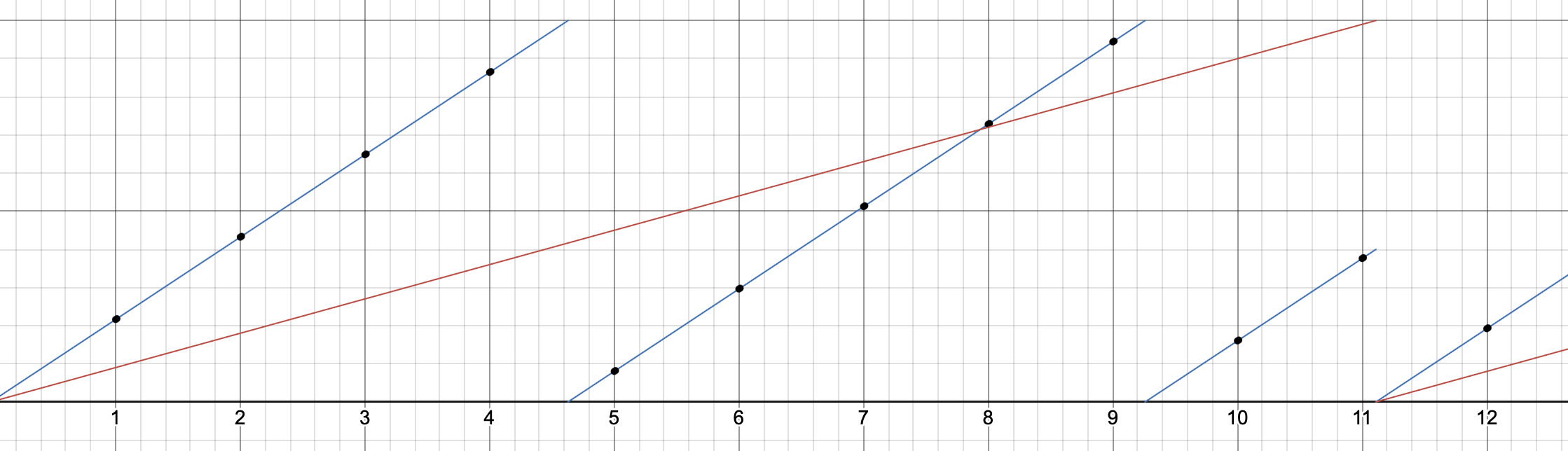
OK so let me try to explain the subsample part with a diagram:
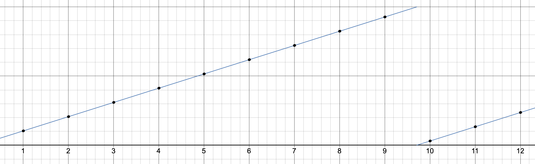
Here's we are zoomed in to a phasor as it is running along, with sample time in the X axis. The conceptual phasor that we are modeling is the thin line; the actual samples we are outputting are the black dots.
Notice how the phasor wraps somewhere between sample 9 and sample 10. The phasor does reset to zero, but it does it at about a time value of 9.8 samples. This moment is not present in the sample series output, because the sample rate does not have enough time resolution to render it. The sample series output is hardly ever going to exactly hit zero, because it hardly ever happens to line up to an exact sample time. In the image above, by the time we get to the end of the sample where the reset happened (where x=10), the phasor has already started rising a bit, so our sample value is not zero.
The same happens when we sync one phasor to another:
When we sync one phasor to another, the sync also happens at some subsample location between one sample frame and another. That also means that the output sample value is not likely to be zero either, but some number slightly above zero, representing how much the phasor has risen in the remaining fraction of a sample after the actual reset happened.
That's why we have the extra + operator after the round in the go.ramp.div patcher -- that's exactly what it is doing. The round operator is figuring out the phasor value at the instant of the reset sync, and then the + operator is adding on the rise for the remaining fraction of the sample frame in which the sync happened.
Hopefully that helps clarify things.
To answer the other questions:
The Left part of this patch is like a sync detector right? But it will only function when the Original phasor sends a trigger(when wrapped), does that mean if I make a sync attempt within the one cycle of the Original phasor,this sync attempt will be “latched” until next wrap point?
Yes, that's the way this particular patch was designed. You can remove this feature by removing the go.latchsync if you prefer. Or you could add a param to enable or bypass the go.latchsync to have the option.
So if our Original phasor is very slow, and we use this divider as a multiplier,we change the ratio within one cycle multiple times, does that mean all those changes will be unsynced?cas the right inlet of the last switch will send out the new phasor ramp Immediately whenever the ratio changed
Yes that is how it will behave.
Another question is, what is the “sync” mean in this patch? does it mean the follower phasor should start at 0 phase(the start Position)when our Original phase wrap and starts from the Beginning?
No, it will align to the nearest valid integer subdivision, because of the round operator. That might be 0 phase, or it might be some multiple of 1/ratio.
if so,along with the latch function we mentioned before,why shouldn't we just trunc or reset the Position of our new phasor,then add the “sub-sample accurate”value back whenever our Original phasor finish a cycle and sent a trigger,this will make sure these 2 will always be synced at the start of the Orginal phasor?
If that is the behaviour you prefer then I encourage you to make a copy of the patch with the round removed, or with a param to have the option to bypass the round as suggested earlier.
I want to re-emphasize a point we make several times in the book -- that all the patches in the book are intended as material to be explored and modified further. Quite often in the book we build up a patch part by part, starting from a relatively simple structure then adding more refinements as we encounter the need for them -- and you're very strongly encouraged to do the same! (We also did this for this very patch -- starting from a much simpler patch.)
Our hope was that in doing so, we help to give ideas about what these could be and how to achieve them -- both conceptually and technically. Hopefully it also helps to highlight some of the more subtle issues that can crop up -- such as in this case the subtleties of subsample accuracy, the edge cases for sync reset, and so on, and this thread has also shown how many different behaviours could be seen as preferable in one situation or another.