
Reset message to Arduino from Max?

Hi all,
tl;dr - is there a message I can send via the serial object to a connected Arduino to restart or reconnect? (Or, I suppose, a bit of code I can add to my sketch to monitor the connection and restart it if it drops.)
Detail: I have 3 capacitance keyboards (mpr121) connected via a multiplexer to an Arduino Micro. I’ve created a sketch (not being that much of an Arduino programmer) from various sketches available online. And that seems to be working well.
However, from time to time the Arduino connection drops. Data stops arriving, and the orange led on the Arduino showing I2C data arriving goes off.
I’ve tried open/close/reset messages to [serial] in my Max patch, but although they work during “normal operation”, they won’t restart the connection once it drops. The only way I can currently fix this is to pull the USB lead and plug it back in, then reselect the appropriate modem input to [serial].
It would be useful if there is a way of doing this, as I’ve put together several new sensor systems which all use Arduino Micros (as opposed to the Phidgets and BareConductive boards I currently use). I’m going to try them out in a workshop next week, and it would be great if I can restart things from my main Max patch instead of having to keep dis/re-connecting devices if the connection drops.
thanks
David

my advice would be to use 32u4 based micros as HID devices instead of serial.
There are several reasons for that, not only becuse serial connection seems to break from time to time, in first place on windows,
but also to be able to distinguish devices
if multiple are used at same time.
To allways get THAT micro into THAT serial object in Max
no matter in which USB port, slot, HUB, order etc they get connected is not a trivial task.
------
I have used many 32u4 based boards with modified USB descriptors
as Joystick devices on both Mac and Windows.
joystick mode is better because keyboards and mice are not allowed as HID devices in Windows OS.
Back to your request ...
Resetting serial on 32u4 boards would be possible if you insert
while(! Serial);
in void setup()
which causes native USB Arduinos to run setup routine
when one reopens serial port.
Same as other USB to serial like CH340 or ftdi devices do.
---
But the question is why really your micro stops working,
i2c buss not working means complete stall of the main loop
which is reading it.
Are you sending too much and too fast data ?
In that case restarting Aurduino would not help much.
------
anyway, here is link to one of many posts I posted over the years to deal with multiple boards:
https://cycling74.com/forums/rename-serial-ports-using-arduino
I would wote against midi mode due to several restrictions, but use joystick !!!
------
P.S. If you decide to go that way, I would post newer instruction for boards which work well at least till last IDE 1.8.19. I don't use Arduino 2 because I don't run any OS that supports that version. In short - there is no need to fiddle with any usb descriptors etc for joystick variants, only to add new definitions in bords.txt file.
hi Source Audio, and thanks for replying...
first -
>But the question is why really your micro stops working, i2c buss not working means complete stall >of the main loop which is reading it. Are you sending too much and too fast data ?
I did wonder that. My concern is that if the loop runs too slowly, the "touchkeys" will feel unresponsive. (This is perhaps made a little more complicated because I'm using proximity rather than touch - the copper sensors are underneath a sheet of 2mm acrylic and another 1mm foam to reduce impact.)
So I reduced the baud rate to 19200, and increased the loop delay to 100ms (from 50ms), and am letting it run now to see if it still stops working (might take a while).
(By the way, the yellow LED I was referring to is the "data send" LED, but you probably figured that out).
>Resetting serial on 32u4 boards would be possible if you insert while(! Serial);in void setup()
The current sketch has while (!Serial); delay(100);
(I'll post the Arduino code in a separate post, in case you want to look at it)
>To allways get THAT micro into THAT serial object in Max
I haven't had a problem with that (yet! AFAIK!). I have a menu listing all of the available serial ports attached to the serial object in each patch that uses it ( the menu is refreshed when the patch is loaded). So I can either manually select which device is read by each [serial] or, in the case of permanent installations, where I know which USB port each device is connected to, use a text file read on load up which contains a list of port names to distribute to each of the relevant sub patchers.
Using [hi]...
I've had a poke around the Arduino examples, and loaded the Keyboard and Mouse libraries, but haven't managed to find something that I can add to my sketch which shows me how to send the sensor data via an HID connection.
I have modified the sketch so that the board shows up as a HID device, though haven't tried more than one connected keyboard yet. Also a little concerned by the warnings that I need a physical "connection on/off" switch. I don't really want to add any additional complications for teachers using the permanent installation!
If I select a device in [hi], that is sending either keyboard or mouse data, but I haven't set that up as an input device in the (Mac) system settings, does that mean that any data that comes over that connection _won't_ affect the mouse cursor?
And presumably the data stream (Filt0: 12 values; Filt1: 12 values etc) is just output from the [hi] object as a stream of labelled data?
Sorry if this is a bit confused - I'm somewhat out of my comfort zone here!)
Can you point me to a sketch which shows sending data via HID, that I can copy into my existing sketch?
thanks
David (Arduino sketch follows)
It is more important to know if you only use on/off states
or send raw sensor data.
Which makes HUGE difference.
If only on/off states, all would be quite easy.
You set threshold, then send only when state of one sensor changes.
I would avoid using key or mouse HID.
Current arduino joystick lib suports 32 buttons,
11 analog inputs and hat switches.
P.S.
That can be modified for more buttons - to match your 36 touch senors.
Here's the sketch for the 3 mpr121s (touch sensors) connected via the first three ports on a TCA9548A multiplexer to an Arduino Micro. There may well be unnecessary bits of code in here. Also, I've only just added the Keyboard.h related commands , which has renamed the available device in the [serial] menu, and allowed the micro to show up in the [hi] menu.
Note, in void(loop)
for (uint8_t t=0; t<3; t++) - t<3 is because there will only ever be a max of three attached touch sensitive keyboards.
the definition of pinscanArray is at the bottom of the sketch
#include "Wire.h"
#include <Adafruit_Sensor.h>
#include <Adafruit_MPR121.h>
#include <Keyboard.h>
#define TCAADDR 0x70
#ifndef _BV
#define _BV(bit) (1 << (bit))
#endif
Adafruit_MPR121 cap = Adafruit_MPR121();
Adafruit_MPR121 cap2 = Adafruit_MPR121();
Adafruit_MPR121 cap3 = Adafruit_MPR121();
int sensorsAt[] = {-1, -1, -1, -1, -1, -1, -1, -1};
void tcaselect(uint8_t i) {
if (i > 7) return;
Wire.beginTransmission(TCAADDR);
Wire.write(1 << i);
Wire.endTransmission();
}
// Keeps track of the last pins touched
// so we know when buttons are 'released'
uint16_t lasttouched = 0;
uint16_t currtouched = 0;
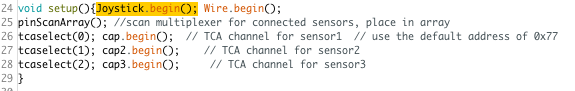
void setup()
{
while (!Serial); delay(100);
Serial.begin(19200);
while (!Serial) ;
Keyboard.begin();
Wire.begin();
pinScanArray(); //scan multiplexer for connected sensors, place in array
tcaselect(0); // TCA channel for sensor1
cap.begin(); // use the default address of 0x77
tcaselect(1); // TCA channel for sensor2
cap2.begin(); // use the default address of 0x77
tcaselect(2); // TCA channel for sensor3
cap3.begin(); // use the default address of 0x77
}
void loop()
{
for (uint8_t t=0; t<3; t++) {
int x = sensorsAt[t];
if (x != -1) //check to see that a sensor is connected to the muliplexer port
{
tcaselect(x);
//following code from Adafruit sketch for the mpr121
{currtouched = cap.touched();
for (uint8_t i=0; i<12; i++)
// reset our state
lasttouched = currtouched;
Serial.print("Filt");Serial.print( x ); Serial.print(": ");
for (uint8_t i=0; i<12; i++) {
Serial.print(cap.filteredData(i)); Serial.print("\t");
}
Serial.println();
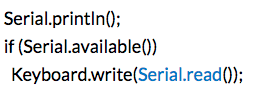
if (Serial.available())
Keyboard.write(Serial.read());
// put a delay so it isn't overwhelming
delay(100);
}
}
}
}
void pinScanArray() {
for (uint8_t t=0; t<8; t++) {
tcaselect(t);
Serial.print("TCA Port #"); Serial.println(t);
for (uint8_t addr = 0; addr<=127; addr++) {
if (addr == TCAADDR) continue;
Wire.beginTransmission(addr);
if (!Wire.endTransmission()) {
Serial.println(t); Serial.println(addr,HEX);
sensorsAt[t] = t;
}
}
}
for (int i = 0; i<7; i = i + 1) {
Serial.println(sensorsAt[i]);
}
}
I’m sending raw data, as it’s _much_ easier for me to handle/parse the data in Max (where I mostly know what I’m doing) than in the arduino (where I don’t have an embedded feel for how the code works).
also, because it’s useful to be able to change the threshold on the fly, depending on whether kids are playing the boards with a finger tip or their whole hand.
here is simplest joystick code
#include "Joystick.h"
Joystick_ Joystick(JOYSTICK_DEFAULT_REPORT_ID,JOYSTICK_TYPE_GAMEPAD,
36, 0, false, false, false, false, false, false, // 36 buttons activated , hatswitch & 6 axis set to 0 / false = deactivated(true = activated)
false, false,false, false, false); // Rudder, Throttle, Accelerator, Brake, Steering, set to false = deactivated
int SW1; int exSW1; int SW2; int exSW2;
void setup() {for (int pin = 2; pin < 8; pin++){pinMode(pin, INPUT_PULLUP);}
Joystick.begin();}
void loop() {
int SW1 = digitalRead(2); if (SW1 != exSW1) {Joystick.setButton(0, 1-SW1); exSW1 = SW1;}
int SW2 = digitalRead(3); if (SW2 != exSW2) {Joystick.setButton(35, 1-SW2); exSW2 = SW2;}
delay(10); // slow down if not needed this fast
}
-------
it uses 36 button addresses, only 1st and last are added to
main loop, just to show how to address them. (0 - 35)
all you need to do is to assign each of your 36 readings to button number.
Can you tell me the name of the joystick library you use? I can't see anything called Arduino Joystick or plain Joystick in my Library Manager.
...
Found it- - this one, presumably
https://github.com/MHeironimus/ArduinoJoystickLibrary
https://github.com/MHeironimus/ArduinoJoystickLibrary/
Thanks for that. I'm going to have to think about it for a while to figure the rest out and how it might fit together.
Does the Joystick library just send the captured values over USB as is? There's no equivalent of Serial.print needed?
No, there is no need to print anything.
I looked a bit at your code.
you could bundle multiplexer instances to form button numbers
for channel 1: for (i = 0, i < 12, i++) button = i;
for channel 2: for (i = 0, i < 12, i++) button = i+ 12;
for channel 3: for (i = 0, i < 12, i++) button = i+ 24;
while iterating though 0 - 11 you check if state changed
and send only if it does.
> while iterating though 0 - 11 you check if state changed and send only if it does.
So I would need to set a threshold value for each key in the sketch, and the state change would be whether the value from the key was above or below that threshold?
The raw values from each key are quite "nervous" and vary around a different average. eg at the start of a particular day, key 1 value might be 53+/- 1, key 2 might be 58+/- 2, and so on. And based on my experience using the BareConductive board (basically an mpr121 with some extra circuitry), these threshold values will change during the day as the touchboard is used - it's affected by room humidity and how much moisture is transferred from the users' hands onto the top surface.
Which is why I also abandoned setting threshold values in the BareConductive sketch; it made more sense to send raw data and deal with it in Max.
[My main reason for trying to use Arduino is that it will allow me to have several (in this case 3) touch sensitive boards on one USB port - at the moment, using BareConductive and Phidget boards, I can only have one board per port (max of 4 usb connections, as that's what's available on the usb/ethernet link I'm using), and I want to add some short and long range ToF laser sensors to the mix, so that I can have more input devices running at the same time.
So far, I don't seem to be having the dropping connection problem with the distance sensors (2 sensors per mpx/micro system). I've got a workshop next week, so I'll get the chance to try those out running all day, even if I can't get the touch board system bit working reliably by then.]
[I've got 2 of these boards running on a single Micro into Max using serial, with the slowed down baud rate and loop speed in the sketch, and am waiting to see if the loop stops/connection drops (whichever it is). The response time is not great, so if it doesn't hang I'll try shortening the loop delay or increasing the baud rate to see what happens.]
I am on the run, try this code, mybe it has mistakes
#include "Wire.h"
#include <Adafruit_Sensor.h>
#include <Adafruit_MPR121.h>
#define TCAADDR 0x70
#ifndef _BV
#define _BV(bit) (1 << (bit))
#endif
#include "Joystick.h"
Joystick_ Joystick(JOYSTICK_DEFAULT_REPORT_ID,JOYSTICK_TYPE_GAMEPAD,
36, 0, false, false, false, false, false, false, // 36 buttons activated , hatswitch & 6 axis set to 0 / false = deactivated(true = activated)
false, false,false, false, false); // Rudder, Throttle, Accelerator, Brake, Steering, set to false = deactivated
Adafruit_MPR121 cap = Adafruit_MPR121();
Adafruit_MPR121 cap2 = Adafruit_MPR121();
Adafruit_MPR121 cap3 = Adafruit_MPR121();
int sensorsAt[] = {-1, -1, -1, -1, -1, -1, -1, -1};
void tcaselect(uint8_t i) {
if (i > 7) return;
Wire.beginTransmission(TCAADDR); Wire.write(1 << i);Wire.endTransmission(); }
uint16_t EXtouch1 = 0; uint16_t touch1 = 0; uint16_t EXtouch2 = 0; uint16_t touch2 = 0; uint16_t EXtouch3 = 0; uint16_t touch3 = 0;
void setup(){Wire.begin();
pinScanArray(); //scan multiplexer for connected sensors, place in array
tcaselect(0); cap.begin(); // TCA channel for sensor1 // use the default address of 0x77
tcaselect(1); cap2.begin(); // TCA channel for sensor2
tcaselect(2); cap3.begin(); // TCA channel for sensor3
}
void loop() {tcaselect(0); touch1 = cap.touched();
for (uint8_t i=0; i<12; i++) {if ((touch1 & _BV(i)) && !(EXtouch1 & _BV(i)) ) {Joystick.setButton(i, 1);}
if (!(touch1 & _BV(i)) && (EXtouch1 & _BV(i)) ) {Joystick.setButton(i, 0);}} EXtouch1 = touch1;
tcaselect(1); touch2 = cap.touched();
for (uint8_t i=0; i<12; i++) {if ((touch2 & _BV(i)) && !(EXtouch2 & _BV(i)) ) {Joystick.setButton(i+12, 1);}
if (!(touch2 & _BV(i)) && (EXtouch2 & _BV(i)) ) {Joystick.setButton(i+12, 0);}} EXtouch2 = touch2;
tcaselect(2); touch3 = cap.touched();
for (uint8_t i=0; i<12; i++) {if ((touch3 & _BV(i)) && !(EXtouch3 & _BV(i)) ) {Joystick.setButton(i+24, 1);}
if (!(touch3 & _BV(i)) && (EXtouch3 & _BV(i)) ) {Joystick.setButton(i+24, 0);}} EXtouch3 = touch3;
}
void pinScanArray() {for (uint8_t t=0; t<8; t++) {tcaselect(t);
for (uint8_t addr = 0; addr<=127; addr++) {if (addr == TCAADDR) continue;
Wire.beginTransmission(addr);if (!Wire.endTransmission()) {sensorsAt[t] = t;
}}}}
Thanks for that.
It's compiling ok, but nothing happens when I upload it (I tried dis/reconnecting the usb plug to make the board restart after uploading. Is that ok, or do I need to actually press the reset button on the board?)
[hi] can see the Arduino ok, but no messages received.
Is the orange LED meant to flash (it isn't) or is that just when sending serial data?
I disconnected the copper sensors from one of the boards, so that I can touch the mpr121 pins directly, as the sketch looks to me like it's watching for touch specifically.
I also removed the 3rd input from the sketch, in case loop failed because there isn't currently anything connected to that third pin on the multiplexer.
I've got to go and cook supper now, so I'll probably get back to this in the morning.
Thanks again for your help so far. Much appreciated.
I tried to merge your code with simple joystick while sitting in the train without arduino IDE at hand.
I expected it would have some mistakes - but not such a trivial one :
I forgot to activate joystick in void setup()
add this:
void setup() {Joystick.begin(); wire.begin()
otherwise nothing gets sent out.
Sorry to have wasted your time.
I have no touch sensor and multiplexer a hand to test that,
the code should serve as idea how to deal with the measured
values.
You can also use serial version of it to verify correct capturing.
instead of Joystick.setButton(i, 1);
Serial.print(i); Serial.println(" 1");
In Max hi object shoud output buttons with IDs 2 - 37
on Mac.
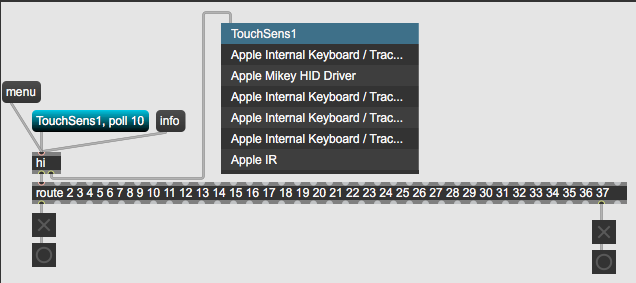
to have board get that unique indentifier, paste this at the and in boards.txt
##############################################################
TouchSens1.name=TouchSens1
TouchSens1.upload.tool=arduino:avrdude
TouchSens1.upload.protocol=avr109
TouchSens1.upload.maximum_size=28672
TouchSens1.upload.maximum_data_size=2560
TouchSens1.upload.speed=57600
TouchSens1.upload.disable_flushing=true
TouchSens1.upload.use_1200bps_touch=true
TouchSens1.upload.wait_for_upload_port=true
TouchSens1.bootloader.tool=arduino:avrdude
TouchSens1.bootloader.low_fuses=0xff
TouchSens1.bootloader.high_fuses=0xd8
TouchSens1.bootloader.extended_fuses=0xcb
TouchSens1.bootloader.file=caterina/Caterina-Leonardo.hex
TouchSens1.bootloader.unlock_bits=0x3F
TouchSens1.bootloader.lock_bits=0x2F
TouchSens1.build.mcu=atmega32u4
TouchSens1.build.f_cpu=16000000L
TouchSens1.build.vid=0x2342
TouchSens1.build.pid=0x1138
TouchSens1.build.usb_product="TouchSens1"
TouchSens1.build.usb_manufacturer="AS-2023"
TouchSens1.build.board=AVR_LEONARDO
TouchSens1.build.core=arduino:arduino
TouchSens1.build.variant=arduino:leonardo
TouchSens1.build.extra_flags={build.usb_flags}
##############################################################
each unique board must get unique name and pid
Good morning!
After a bit of fiddling around, that code is working. Cool!
and
> while sitting in the train without arduino IDE at hand.
I'm impressed. You clearly know this stuff really well.
I copied the naming script into boards.txt, but the board is still showing up in [hi] as "Arduino Micro". Is there something else I need to do to activate the naming? (I restarted the Arduino IDE and reloaded the sketch before re uploading it to the board).
(This is the version of boards.txt I added it to -
/Users/davidstevens/Library/Arduino15/packages/arduino/hardware/avr/1.8.6
the only other boards.txt in the Arduino15 folder was one that belongs to the ArduinoBLE, and I'm not using that board at the moment
)
But basically, yes, working. The other Micros are sending data via serial (continuous distance data), so maybe the naming doesn't matter as long as I only use [hi] with the one board?
However, and unfortunately...
this way of sending data from the touch keyboards to Max only works if I touch the (copper) sensors directly (actually, it still works with a layer of baking paper on top of the keys). With the painted acrylic sheet on top of the keys, touch isn't detected by the mpr121. So either I use the serial method, or I figure out a way to make the sensors actually touchable. My constraint here is that these keyboards are for use with SEN kids, and I don't want them to be able to touch the keys directly for practical reasons (some of them will almost certainly pick at the copper until it pulls up) and for aesthetic reasons (the painted surface interacts with the changing colours from the large LED lights in the room that are controlled by the keys touched and the other sensors). I could paint directly over the copper, and touch might still work, but that looks ugly (I've done something similar before with conductive paint) and also requires me to expose the tops of the small bolts connecting the copper to the cables to the electronics.
Though I see I can change the threshold values, so I'll have a play with that and see if I can make the sensors more responsive.
So not entirely sure which way I'll go with this yet, but thanks very much for the help with the joystick connection - that adds a chunk more to my ability to use arduinos with my system.
I am again on the run ...
boards.txt file - it depends where your hardware libs are.
If you did not update boards from original installed with Aruino,
that will be inside of Arduino.app/Contents/Java/hardware/arduino/avr/boards.txt
If you did update, then in documents following same structure.
You need to select it in Arduino to upload the code to it...
----------------
You can very well adjust thresholds for touch detection.
That is a way to go I think.
The problem with your original code maybe is that
you were prining both raw data and touch states.
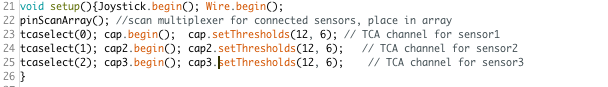
Struggling (surprise) with the threshold setting code. I presume that it needs to go in void (setup); and I've defined the 2 variables (touch and release) just before that. The command for the Adafruit library I'm using is
setThresholds(touch, release);
Do I need to #define setThresholds or something?
I've labelled the offending line in the snippet below the error message.
====
part of error message (summary - expected primary-expression before 'touch' and before' release'):
/Users/davidstevens/Documents/Arduino/3touchboards_HID/3touchboards_HID.ino: In function 'void setup()':
/Users/davidstevens/Documents/Arduino/3touchboards_HID/3touchboards_HID.ino:36:23: error: expected primary-expression before 'touch'
setThresholds(uint8_t touch, uint8_t release);// TCA channel for sensor1 // use the default address of 0x77
^~~~~
/Users/davidstevens/Documents/Arduino/3touchboards_HID/3touchboards_HID.ino:36:38: error: expected primary-expression before 'release'
setThresholds(uint8_t touch, uint8_t release);// TCA channel for sensor1 // use the default address of 0x77
^~~~~~~
and then the same for the other 2 sensors, then...
^~~~~~~
exit status 1
Compilation error: expected primary-expression before 'touch'
=======
and part of the sketch (everything else is as before), I've bolded the relevant bits:
uint16_t EXtouch1 = 0; uint16_t touch1 = 0;
uint16_t EXtouch2 = 0; uint16_t touch2 = 0;
uint16_t EXtouch3 = 0; uint16_t touch3 = 0;
uint8_t touch = 6;
uint8_t release = 3;
void setup(){
Joystick.begin();
Wire.begin();
pinScanArray(); //scan multiplexer for connected sensors, place in array
tcaselect(0); cap.begin() ;
[line 36] setThresholds(uint8_t touch, uint8_t release);// TCA channel for sensor1 // use the default address of 0x77
tcaselect(1); cap2.begin();
setThresholds(uint8_t touch, uint8_t release); // TCA channel for sensor2
tcaselect(2); cap3.begin();
setThresholds(uint8_t touch, uint8_t release); // TCA channel for sensor3
}
============
As first, I don't know if using adarfuit library with auto
touch detection will work well for you.
That because from what I understand it is not based
on absolute raw reading values which you could use
to set traditional threshold parameters.
from Adafruit_MPR12.cpp lib
The threshold is defined as:
* deviation value from the baseline value, so it remains constant
* even baseline value changes.
------
Anyway, to set that values
you use only 1 line in setup
cap.setThresholds(12, 6);
which has to be done AFTER calling cap.begin() ;
in the docs file it says:
"By default, the touch threshhold is 12 counts, and the release is 6 counts. It's reset to these values whenever you call begin() by the way."
-------
I would think proper place to set threshold values woud be in setup.
But you need to test that.
Other option would be to go traditional way, read raw values,
declare touched and non touched threshold values, set on/off states for each sensor, and than proceed sending states only when changed.
Not too differnt from what adafruit lib does.
P.S.
this is a helpfull link, as Adafruit supporter explains that values a bit better.
https://forums.adafruit.com/viewtopic.php?f=19&t=117274
>I would think proper place to set threshold values woud be in setup
Yes. I swapped out the variables (setThresholds(touch, release);) for fixed values (ie setThresholds(8, 4); )
and most of the error messages have gone. Now I just have
"setThresholds was not declared in this scope"
I don't understand this as setThresholds is part of the library. Surely it's defined when the library is called?
>I don't know if using adarfuit library with auto touch detection will work well for you.
Maybe I should use the regular mpr121.h library that BareConductive use? I'll see if I can find the definitions and see if it's that different.
>Other option would be to go traditional way, read raw values, declare touched and non touched threshold values, set on/off states for each sensor, and than proceed sending states only when changed.
you mean do that in the Arduino code? I'm going to have to think about that for a while!
Though I do wonder if I'm going to come up against the need to change the threshold (however set) on the fly, depending on environmental conditions and/or playing style (it tends to be either whole hand or single finger, which both need different trigger thresholds), and I don't think I can change that from Max once everything is set up?? Which is why I was sending raw data and sorting out the whole threshold thing in Max. But that of course is what started this whole conversation off, with the tradeoff between responsiveness of the sensors and the risk of the loop locking up.
it needs cap.setthresholds(4,8);
or cap2.setthresholds(4,8);
without cap assigned - you get that error.
------
I am sure there must be a resonble way to get that raw data into max
and do all the rest there, but you were doing both at same time-
cooked touch states and raw data.
The question is - is serial reliabe or not ?
If yes, then tame output a bit, remove printing of all useless infos
and send 36 raw values using high baud rate.
---
Or try doing the same using joystick or midi library, which would need some tweaking, but if you can live with 36 7 bit midi controls why not ?
You are Mac user, so midi is not going to bug you.
Another option is - you can use 32u4 board as HID output
and at same time send serial data to it ...
in case you want to set thresholds from max.
Or use analog pot to cycle through some presets .
there are so many options
>it needs cap.setthresholds(4,8);
aha. This is my lack of familiarity with the language.
>but you were doing both at same time
yes, I've eliminated all of the touched/not touched stuff. Reduced loop delay to 75ms and baud to 57600 - stable so far.
In the meantime, while trying to figure out a good way to reduce some of the noisiness of the signal, without reducing responsiveness too much, I had a bit of an epiphany! Instead of finding peak and trough values and setting trigger thresholds, all I really need to do is see if the values are decreasing (note on) or increasing (note off) beyond a certain amount, which is actually pretty simple.
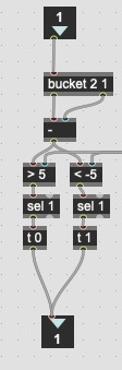
It's not quite there yet, 'cause I get the occasional stuck note (ie the note off is getting missed), but I hope with a bit more tweaking... And something that simple might be easy for me to translate into Arduino speak.
You could do a bit of smoothing in arduino first,
and finalise it in Max.
something like :
if (abs (x - EXx >= 2)){Serial.println(x); EXx = x;}
x is current sensor value, 2 being change in value needed to send it.
You could then send data without any delay,
or a very short one.
75ms is a bit long for real time note trigger .
The idea is not to send list of 36 sensors all the time,
but only ones that do change. And that very fast.
For that you need ID - Value pairs.
Ok, this seems to be mostly working, though I'm still getting values in Max when the values are +/-1 (ie it seems to have reduced but not eliminated all of the +/-1 noise). Especially keys 0 & 1 - they seem to send values even if the value is only slightly changing. Also, one of the boards only has 8 keys, so the last values (8-11) barely change, but they are still being sent. There's something here I'm not understanding.
I tried bigger values (up to 10) for the comparison ( the function you suggested), but although it reduced the data a lot, the boards became too insensitive (they work well if you play with at least 3 fingers touching a key, but lots of kids like to use just 1 finger tip to play).
If I understand correctly, I don't need to define 3 different MPR121 caps, as values are only taken from whichever cap is currently selected by tcaselect() - so eg cap.begin() and cap.FilterData() always only refer to the currently selected mpr121.
There's probably still a bit of redundant code in here (I'm not using the array anymore).
=====================
#include "Wire.h"
#include <Adafruit_Sensor.h>
#include <Adafruit_MPR121.h>
#include <Keyboard.h>
#define TCAADDR 0x70
#ifndef _BV
#define _BV(bit) (1 << (bit))
#endif
Adafruit_MPR121 cap = Adafruit_MPR121();
int sensorsAt[] = {-1, -1, -1, -1, -1, -1, -1, -1};
void tcaselect(uint8_t i) {
if (i > 7) return;
Wire.beginTransmission(TCAADDR);
Wire.write(1 << i);
Wire.endTransmission();
}
uint16_t EXz = 0; uint16_t z = 0;
void setup()
{
while (!Serial)
//Serial.begin(19200);
Serial.begin(57600);
//Serial.begin(115200);
while (!Serial); { delay(100);}
Keyboard.begin();
Wire.begin();
tcaselect(0); // TCA channel for sensor1
cap.begin(); // use the default address of 0x77
tcaselect(1); // TCA channel for sensor2
cap.begin(); // use the default address of 0x77
tcaselect(2); // TCA channel for sensor3
cap.begin(); // use the default address of 0x77
}
void loop() {
tcaselect(0);
Serial.print("Filt");Serial.print( 0 ); Serial.print(": ");
for (uint8_t i=0; i<12; i++) {
int z = cap.filteredData(i);
if(abs(z-EXz>=3)) {
Serial.print(i); Serial.print(" "); Serial.print(z); EXz = z;}
Serial.print("\t");
}
Serial.println();
delay(10);
tcaselect(1);
Serial.print("Filt");Serial.print( 1 ); Serial.print(": ");
for (uint8_t i=0; i<12; i++) {
int z = cap.filteredData(i);
if(abs(z-EXz>=3)) {
Serial.print(i); Serial.print(" "); Serial.print(z); EXz = z;}
Serial.print("\t");
}
Serial.println();
delay(10);
tcaselect(2);
Serial.print("Filt");Serial.print( 2 ); Serial.print(": ");
for (uint8_t i=0; i<12; i++) {
int z = cap.filteredData(i);
if(abs(z-EXz>=3)) {
Serial.print(i); Serial.print(" "); Serial.print(z); EXz = z;}
Serial.print("\t");
}
Serial.println();
delay(10);
}
uint16_t EXz = 0; uint16_t z = 0;
shoud it not be
int z =0; int EXz =0;
we iter through individul sensors, not 12 bit array
-----------
I would as first remove all of this:
then use only this :
tcaselect(0); for (int i=0; i<12; i++) { int z = cap.filteredData(i); if(abs(z-EXz>=3)) {Serial.print(i); Serial.print(" "); Serial.println(z); EXz = z;}
tcaselect(1); for (int i=0; i<12; i++) { int z = cap.filteredData(i); if(abs(z-EXz>=3)) {Serial.print(i+12); Serial.print(" "); Serial.println(z); EXz = z;}
tcaselect(2); for (int i=0; i<12; i++) { int z = cap.filteredData(i); if(abs(z-EXz>=3)) {Serial.print(i+24); Serial.print(" "); Serial.println(z); EXz = z;}
-----
in Max use route 0 1 2 3 4 .... 35
I never used that multiplexer and touch sensors.
Can't say if one has to declare completely separated 3 caps
all the way through,
like
Adafruit_MPR121 cap1 = Adafruit_MPR121();
Adafruit_MPR121 cap2 = Adafruit_MPR121();
then cap1.begin();
cap1.filteredData(i);
and so on.
logic says no, because of multiplexer...
But you can test that easy if you hold only few sensors on
for example 2nd board.
Hmm. Looking at the data going into Max, I'm not sure that I've got the sketch right. There's still more than I would expect given the filtering.
wait, I think I made a mistake here.
we need array of 12 items to compare states.
unsigned long z[12] = {0,0,0,0,0,0,0,0,0,0,0,0};
unsigned long EXz[12] = {0,0,0,0,0,0,0,0,0,0,0,0};
then
tcaselect(0); for (int i=0; i<12; i++) { z[i] = cap.filteredData(i); if(abs(z[i]-EXz[i] >=3)) {Serial.print(i); Serial.print(" "); Serial.println(z[i]); EXz[i] = z[i];}
and so on for rest boards.
mistake was that compared states were reset after each match
that might explain why the previous changes didn't work!
And yes, the new version works, though I'm still getting eg board 1, pin 1 54 53 54 53 54 42 rather than 54 . . . . 42. ie a continuous stream of small changes, rather than nothing until there's a change bigger than the comparison. (Unless there are lots of big jumps between those small changes that are too fast for me to see)
And of course I'm now getting a continuous stream of fixed values for the third board, even though it's not connected. But... I think I can fix that in the sketch by adding a <= 200 (eg) to the comparison.
And so that I understand - in this latest version, it's the full array of momentary MPR121 pin values that's being compared at once, rather than iterating through the individual pin values?
Multiplexer - it's all working, only declaring a single
Adafruit_MPR121 cap = Adafruit_MPR121();
so it doesn't need cap1. cap2. etc.
Hmm, I thought this would work, but no...
(z[i]-EXz[i] >=3) & (z[i]-EXz[i]) <=1000)
(z[i]-EXz[i] >=3) & (z[i]-EXz[i]) <=1000) ?????
if you wanted and comparison then
if (a >= b and b =< c )
or
if (a >= b && b =< c )
no need for separation parenthess
but I don't understand really what you read in max.
It should be 2 item lists :
number of sensor - value.
like 3 255 for sensor nr 3
2nd board gets ids 12 -23, 3rd 24 - 37
that 3 iterations read each individual sensor pin.
Thanks. As I may have hinted previously, I may know what I’m doing in Max, but C type languages are out of my area of expertise. I’m trying!
and yes, I’m reading paired values in Max, exactly as you describe. Sorry, in trying to explain I took the first (index) value as given, so didn’t mention it.
so, my understanding of the comparison in the sketch, is that a value from a pin will only be sent out through serial.print if it is sufficiently different from the previous value.
So if the average value is 53, but it is actually varying constantly between 53 and 52, (or more fully, (1 53) and (1 52)) then that value won’t be sent out if the comparison value is set to 3. ( but a jump to (1 50) would be.)
But in Max, once those values have arrived via [route 1 2 etc] into a number box, what I see is the value in [number] going 53 52 53 53 52 etc. Am I misunderstanding something?
No, it should work exactly as you describe.
Only explanation would be that sensor values did
fluctuate more than set threshold.
You can make new minimal test sketch and capture a single sensor
to see what it does.
// Data(0); <-- select sensor number
void loop(){
tcaselect(0);
Serial.print(cap.filteredData(0)); Serial.print(" "); Serial.println(cap.baselineData(0));
delay(10); // set as needed
}
I don't really know what that baseline & filtered Data really is.
It definitely is NOT raw sensor data.
Maybe that makes it difficult.
Original touched or not is based on change between base and filtered
readings, but I have no time to read all that docs to tell you all about it.
The stream of data I'm getting now is perfectly useable, and pretty fast/responsive, so I'm not currently too worried about further refinements. When I'm away next week, I might have a look at a single data stream after work to see what's going on, if only to have a better understanding of the thing. The one thing I do know is that if I increase that comparison value enough to noticeably reduce the data stream, then the keys require much more skin to trigger. which isn't going to accomodate the wide range of possible playing styles.
I've just completely redesigned the max patch that handles this new data stream, and so far it's working really well. It's sufficiently ok that I can try it out with the kids in next week's workshop. Thier playing techniques are much more variable than mine, so it's a much better test of the robustness of what I've done :-) .
Thanks again for all of your help - it's been really valuable.
All well, maybe you are also interested in piezo elements,
quite cheap and can also include velocity - making really responsive drumpads .
I made lots of them for kids ad "real" drummers
yeah, I've thought about piezo elements, and i'll keep that in mind when I'm watching how the kids interact with my instruments next week, and see what might be missing.
I've wanted to make a more "always triggers" floor mat for some time (I use either pressure or capacitance sensors at the moment, and they are less than ideal - the capacitative ones generally need for people to take their shoes off) and have been thinking about microswitches. But piezo would probably be a better way to do it.
Presumably, though, if I had a board with (say) 6 piezos on it, whatever was acting as the actual pad (probably acrylic sheet(s)) would have to be 6 single pieces (ie not one large sheet), and then I have to think about a safe way to fix them. At the moment, on the large single top sheet that I use for the capacitative floor "keyboard", I fix it using large countersunk bolts. I could figure out a tidy way to do that with 6 separate sheets I suppose.
Will piezo elements respond to a fairly low pressure/impact? Though some kids do like to jump on things, so the impact would transmit through the acrylic, some of the ones with balance issues would only be able to step from one "key" to another.
And presumably, you would connect each sensor directly to an analogue pin on the arduino? Or does the signal need some conditioning (I know they are high impedance...)?
quite few things are possible.
One can really wire them directly, and lower analog reference
to increase sensitivity.
But I never used them really as weight measurement,
but really to knock on them or play with my fingers.
They are easy to mount, one can glue them under or onto
pieces of whatever material,
and for better isolation add some rubber under them
in case thay mount close on same surface.
You can also use multiplexers for that if
8 sensors are not enough
Cool! I'll look into that then.
all it needs is 1 - 2 MOhm from each analog in to ground.
Just bought a bunch (+ resistors), and I have an unused Micro sitting around, so...
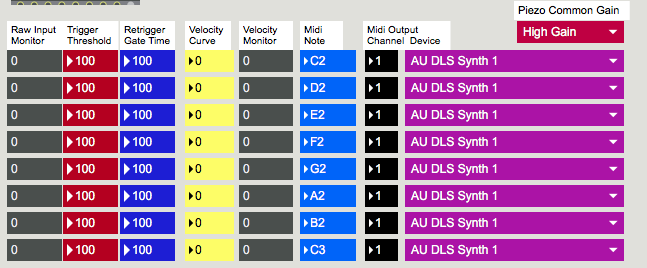
Would you try one of my old patches for 8 Piezos
with indiviual sensitivity and threshold etc control .
Was made for NANO, but one can adapt it for micro,
I can digg it out tomorrow when I get home
Sure. It‘ll be the week after next before I can work on that, but yes. Thanks.
here are 2 variations, simple one with only adjustable general
threshold and overal sensitivity from max
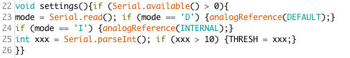
(by switching between default and internal analogReference)
on NANO that makes difference of 5v or 1.1v
On micro, internal is 2.5v, default 3.3v , so you will have no benefit much from that.
Only if you use external analogReference via pot, to lower it
and so get more sensitive inputs.
-----
Second version allows per - pad (piezo) threshold
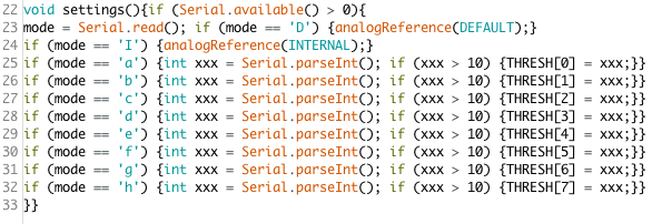
and also this :
max patches were done on max 5 so I need to go through and check
if there are any problems when run in Max 8.
Smaller Micro boards are missing analog inputs A4 and A5
(which actualy are free to connect if you wire pins 40 & 41)
to read pins using for loop

enter pin order to read into array

I'll be back with max patches when I get time to test them
-----
Piezos like this can only be used as one shot triggers
max patch for simple variant
Thanks for all that. I'll let you know how I get on.
I actually have a Nano hanging around - a NanoBLE though, And it's hanging around because I never figured out how to send messages through the Bluetooth port. But it should still work with a serial connection (?)
Sure it will work.
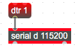
one has to send dtr 1 message to serial
after openning the port to communicate properly with nRF based boards
any board that has enough analog inputs would do.
only defference is analog reference, which depends on processor.