
sample interpolation while reading trough buffer

Dear Forum,
I use a sawtooth table loaded in a buffer of 512 samples to cycle trough it using [cycle~], [phasor~] and [rate~], to build a LFO. Everything is working as I want expect of the moment where the saw is dropping from 1.0 to -1,0. As I read the buffer very slowly the cycle object interpolates the values between the two samples. What I need would be a clean drop in the signal without any intermediate values. Is there something like a "sample & hold" functionality when reading trough a buffer?
Thanks,
Thomas

you cant turn interpolation off, the closest alternative would be to use [wave~]
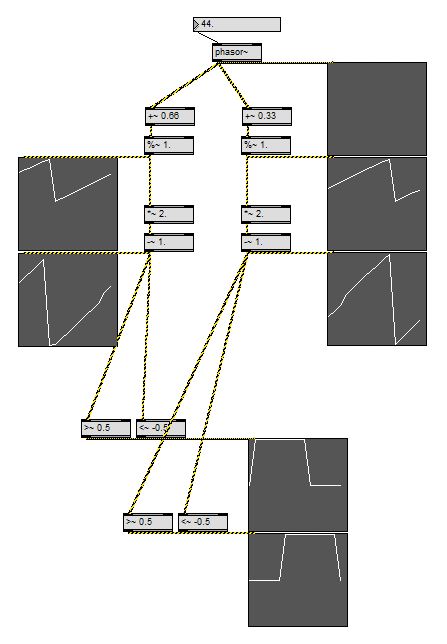
if you only want to produce simple waveforms (such as a sawtooth) you can also avoid using buffers at all and direcly calculate the desired waveform (that is kinda what phasor is made for):
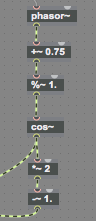
cosine:
phasor~
+~ 0.75
%~ 1.
cos~ (second inlet)
square:
phasor~
>=~ 0.5
sawtooth (down):
phasor~
!-~ 1.
*~ 2.
-~ 1.
frequency multiplier:
phasor~
*~ 5.
%~ 1.
...and so on.
Hey Roman, Thanks for the hint! It is working great and actually solving my initial problem. But with this solution I have another issue coming up:
The nice thing about [cycle~] was that I was able to sync the [phasor~] to the transport (it's for a m4l device) and still being able to change the phase of all waveforms with cycles second inlet.
By calculating the waveform directly I think its not possible to phase all the waveforms. For cosine its easy by adding a value between 0 and 1. But for square, saw up, saw down and triangle I have no idea how to do this. Maybe you know a way?
The only thing I had in mind was working with [delay~], but that seems too heavy as I would need long delay times for slow movement.
You mentioned [wave~] as well. Maybe I could do it by using a buffer of the length of two periods of the waveform, in order to be able to phase by using start and endpoints. But do you think the [wave~] object does no interpolation on the samples as the [cycle~] does? In that case I would have the same problem as before.
Many thanks :)
in wave~ it is on by default, but can be turned off (mode 0)
changing the phase of a phasor using a signal is also possible by processing the signal which comes out of phasor.
phasor~
+~ 0.33
%~ 1.
(=main phasor signal with phase offset)
...and then add one of the waveforms from first post.
in case you dont do it already ... while you program this stuff, always attach a scope~(s) with a range of -2.1 to +2.1 and fast settings such as 64/16, and then choose a phasor speed which exactly fits into the scope size.
this way you can easily find your way how to build all kind of waveforms without knowing all the math by heart.
-110
1. frequency multiplier/divider
2. phase offset
3. scale to range
4. distort to desired waveform
that is the order of the "modules". *)
and you can derive a parallel branch after each of the steps to make different versions - which are all in sync now.
great for making complex waveforms, too, just create the parts and then mix them together.
*) yes, the cosine example already makes use of the same trick. it is part of the algo to make the cosine waveform start at zero.
works like a charm :) many thanks
1.
for cases of future reference i have corrected various typos in the code above (mainly misplaced tildas)
2.
and i also want to add the missing "tri wave oscillator" to the collection now.
the tri wave example below could be further optimised to use a bit less objects.
but i am leaving it like it was on my HD now, because the way it is presented here can serve as good example for the one or other general method of dealing with phasor~ output as carrier signal.
the third thing i´d like to add to this thread is that (i think @encoder audio recently asked something similar) you can not build a proper "clock divider" in this same kindergarten-arithmetic-and-logic manner, only a clock multiplier.
(for clock division you would have to include sh*t like sah~ and accum~ and/or scale the original phasor signal range, so that you loose its key feature to always output exactly 1. for the last sample and beeing able to reset its phase by only resetting the master phasor.)
so what you have to do in situations where you later might want to add a suboscillator to an oscillator, or a"1 bar clock" to a "1/16 note clock" is to set up your "master phasor" with the slowest required frequency - and then upscale to an artificial "base frequency" from that.
in the case of an oscillator beeing played at 440 Hz it could look like that:
"440."
/ 8.
phasor~
*~ 8
%~ 1.
yourwhateverOSC~
if you now need a /4 frequency divided sub-phasor signal derived from the master phasor you can get it by clock multiplication of *2-to-the-base.
"440."
/ 8.
phasor~
*~ 2 . . . . . (8/4=2)
%~ 1.
alles klar?
and now enjoy! the tri wave generator.
#P window setfont "Sans Serif" 14.;
#P window linecount 3;
#P comment 155 310 163 9109518 map the segments to the desired range to "draw" tri wave;
#P window linecount 2;
#P comment 129 569 100 9109518 tri wave oscillator;
#P window linecount 1;
#P comment 320 55 100 9109518 reset phase;
#P user scope~ 754 550 854 600 64 3 16 -1.04 1.04 0 0. 0 0. 255 255 255 85 85 85 0;
#P user scope~ 754 501 854 551 64 3 16 -1.04 1.04 0 0. 0 0. 255 255 255 85 85 85 0;
#P user scope~ 754 452 854 502 64 3 16 -1.04 1.04 0 0. 0 0. 255 255 255 85 85 85 0;
#P window setfont "Sans Serif" 9.;
#P newex 626 399 50 9109513 sig~ 1.;
#P window setfont "Sans Serif" 14.;
#P window linecount 2;
#P comment 755 406 100 9109518 segments control;
#P window setfont "Sans Serif" 9.;
#P window linecount 1;
#P newex 554 433 82 9109513 gate~ 3;
#P user scope~ 383 133 483 183 64 3 16 -1.04 1.04 0 0. 0 0. 255 255 255 85 85 85 0;
#P flonum 194 76 35 9 0 0 0 139 0 0 0 221 221 221 222 222 222 0 0 0;
#P newex 257 247 51 9109513 -~ 1.;
#P newex 257 273 51 9109513 *~ 4.;
#P newex 93 260 143 9109513 110.map~ 0.25 0.75 1. -1.;
#P newex 24 259 51 9109513 *~ 4.;
#P user scope~ 130 495 230 545 64 3 16 -1.04 1.04 0 0. 0 0. 255 255 255 85 85 85 0;
#P newex 131 433 173 9109513 selector~ 3;
#P newex 585 335 51 9109513 *~ 3.;
#B color 12;
#P newex 512 335 51 9109513 *~ 2.;
#B color 12;
#P newex 513 301 51 9109513 ==~ 0;
#B color 12;
#P newex 586 281 51 9109513 >=~ 0.75;
#B color 12;
#P newex 446 281 51 9109513 <~ 0.25;
#B color 12;
#P message 317 79 50 9109513 0.;
#P toggle 58 64 15 0;
#P newex 58 93 84 9109513 dac~;
#P newex 227 106 84 9109513 phasor~ 43.5;
#P window setfont "Sans Serif" 14.;
#P window linecount 2;
#P comment 650 311 199 9109518 splitting the range into thre segments;
#P window linecount 1;
#P comment 192 53 100 9109518 freq;
#P connect 10 0 11 0;
#P connect 10 0 19 0;
#P connect 9 0 11 0;
#P connect 9 0 19 0;
#P connect 6 0 11 0;
#P connect 6 0 8 0;
#P connect 6 0 19 0;
#P connect 2 0 13 0;
#P connect 2 0 14 0;
#P connect 2 0 16 0;
#P connect 2 0 18 0;
#P connect 2 0 6 0;
#P connect 2 0 7 0;
#P connect 19 2 24 0;
#P connect 19 1 23 0;
#P connect 19 0 22 0;
#P connect 21 0 19 1;
#P connect 7 0 8 0;
#P connect 7 0 10 0;
#P connect 15 0 11 3;
#P connect 16 0 15 0;
#P connect 14 0 11 2;
#P connect 13 0 11 1;
#P connect 11 0 12 0;
#P connect 8 0 9 0;
#P connect 5 0 2 1;
#P connect 17 0 2 0;
#P connect 4 0 3 0;
#P window clipboard copycount 28;
save as 110.map
#P window setfont "Sans Serif" 9.;
#P window linecount 1;
#P newex 21 52 75 196617 clip~ $1 $2;
#B color 2;
#P hidden newex 215 188 116 196617 bgcolor 100 100 200;
#P outlet 21 211 15 0;
#P newex 118 193 37 196617 +~ 0.;
#P newex 21 175 37 196617 *~ 0.;
#P newex 21 144 37 196617 /~ 0.;
#P newex 232 129 37 196617 t b f;
#P newex 232 157 37 196617 - 0.;
#P newex 118 98 37 196617 t b f;
#P newex 118 126 37 196617 - 0.;
#P newex 21 80 37 196617 -~ 0.;
#P inlet 21 30 15 0;
#P inlet 289 30 15 0;
#P inlet 232 30 15 0;
#P inlet 175 30 15 0;
#P inlet 118 30 15 0;
#P newex 358 44 50 196617 loadbang;
#P newex 289 62 50 196617 f $4;
#B color 2;
#P newex 232 62 50 196617 f $3;
#B color 2;
#P newex 175 62 50 196617 f $2;
#B color 2;
#P newex 118 62 50 196617 f $1;
#B color 2;
#P comment 244 210 100 196617 -110;
#P connect 9 0 4 0;
#P connect 5 0 1 0;
#P connect 5 0 2 0;
#P connect 5 0 3 0;
#P connect 5 0 4 0;
#P connect 15 1 14 1;
#P connect 4 0 14 0;
#P connect 15 0 14 0;
#P connect 3 0 18 1;
#P connect 3 0 15 0;
#P connect 8 0 3 0;
#P connect 7 0 2 0;
#P connect 13 1 12 1;
#P connect 17 0 18 0;
#P connect 2 0 12 0;
#P connect 13 0 12 0;
#P connect 1 0 11 1;
#P connect 1 0 13 0;
#P connect 6 0 1 0;
#P connect 14 0 17 1;
#P connect 12 0 16 1;
#P connect 18 0 19 0;
#P connect 16 0 17 0;
#P connect 11 0 16 0;
#P connect 21 0 11 0;
#P connect 10 0 21 0;
#P window clipboard copycount 22;

Hi Roman,
As your here and talking about LFO's, rather than start a new thread can I just ask this quickly;
How does one prevent a bipolar LFO signal from rippling on low notes? :
Hope Bermuda was fun, I couldn't afford it.
while it sounds nice it is probably not what you expected. :)
you are modulating the frequency, which is e.g at 440 Hz, on the hertz layer, so that you end up with e.g. one time 1440 Hz and one time -1000 Hz. (which sounds almost as +1000Hz )
what you want to do is insert the *~ modulation before the mtof
1. because it will go as much up as down and
2. because you can now be sure not to fall under 0 Hz. (even a + -777 modulation of note number -25 will still be more than 0 Hz)
your depth parameter will show up as "relative note numbers"then, for example you could limit it to 48. (four octaves in both directions.)
(in some cases you might want to work on the Hz layer, but then use *~ and not +~ to stay in a range of -n to +n)
and while it should not make a difference, i would swap the operators at the mod depth *~ 0.
Thank-you!, that makes sense.
If this bipolar set up (with the modulation taking place before the [mtof] object) is used with a [coll] object for frequency values instead of [mtof] ....can one smooth the steps between the values?
[line~] with high ramp values works but this obviously has undesirable results when playing notes.