
Patch following music to control motor. work in progress ;)

look at this :
1~ simpler phase switch, you can build it into subpatch
2~ change 0. is not controlling the gate at all, try to move float 0. > 0. and back ....
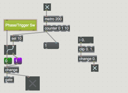
sel 0. allready blocks output of meter~ when there is no input signal.

Good evening,
I wish you the best best for this very square (and not scared) year!
I changed the patch as you said in the last post.
In addition, I changed the use of button rotStep as an adder to the rev counter. If the button reaches three then rev counter[3] adds 1.
I will control rotstep with an LFO from Live. As below
Finally, I wanted to calculate the real position of the motors according to their position and the number of rotations. But when the motors make a turn, the real positions are poorly computed as we can see in the console highlighted in blue. Computing is bad because rev couter bugs.
In my example I made a continuous rotation. So speed should be always the same.
I hope the solution will be easy for you. Thanks teacher ;)
I wish you also all the best in new year !
to be honest, I allways need quite some time to shape your uploaded patches
to try to understand what is the state, and what is it that you ask for.
Most difficulty is that all your patchcords get routed (fragmented) in a way
that it is hard to follow where they go.
You did actually not fix switching of phases at all.
To start with, here is last working patch with proper phase switching
and replaced colls. lists are now in 2 umenus.
switch itself is in all-controls patcher, where it should be.
......
Now to that new stuff ...
to start with :
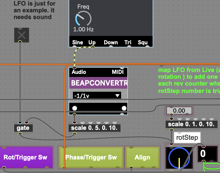
can you use this extract to patch and explain using ONLY this objects
what you really want from that LFO . "... it needs sound ???"
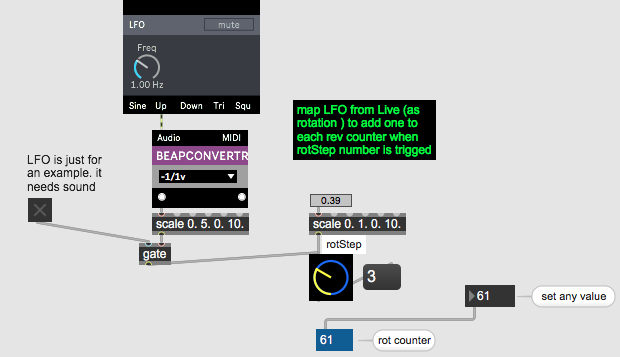
I want to know what is that scale with float ???? doing there ?
and what should output of that LFO/BEAP represent ?
think that rotStep is endless dial usng INTS only !
and explain also what should effect be when CW vs CCW...
..........................
that rotation counter is a fake and will remain a fake.
rotation is absolute value and rotation counts no matter if rotated cw or ccw,
if you have a wheel, and it turned 100 times in whatever direction
2r π * rotation -> you have traveled distance.
your rotation is imaginary and I don't know
how can you really count the movement.
if you would really use arduino and insert rotation report from motors and report it
then ok.
Thanks!
2 umenus work perfectly!!
I use integer to trig rev counter as I explain here.
Actually I will use a signal from Ableton Live.
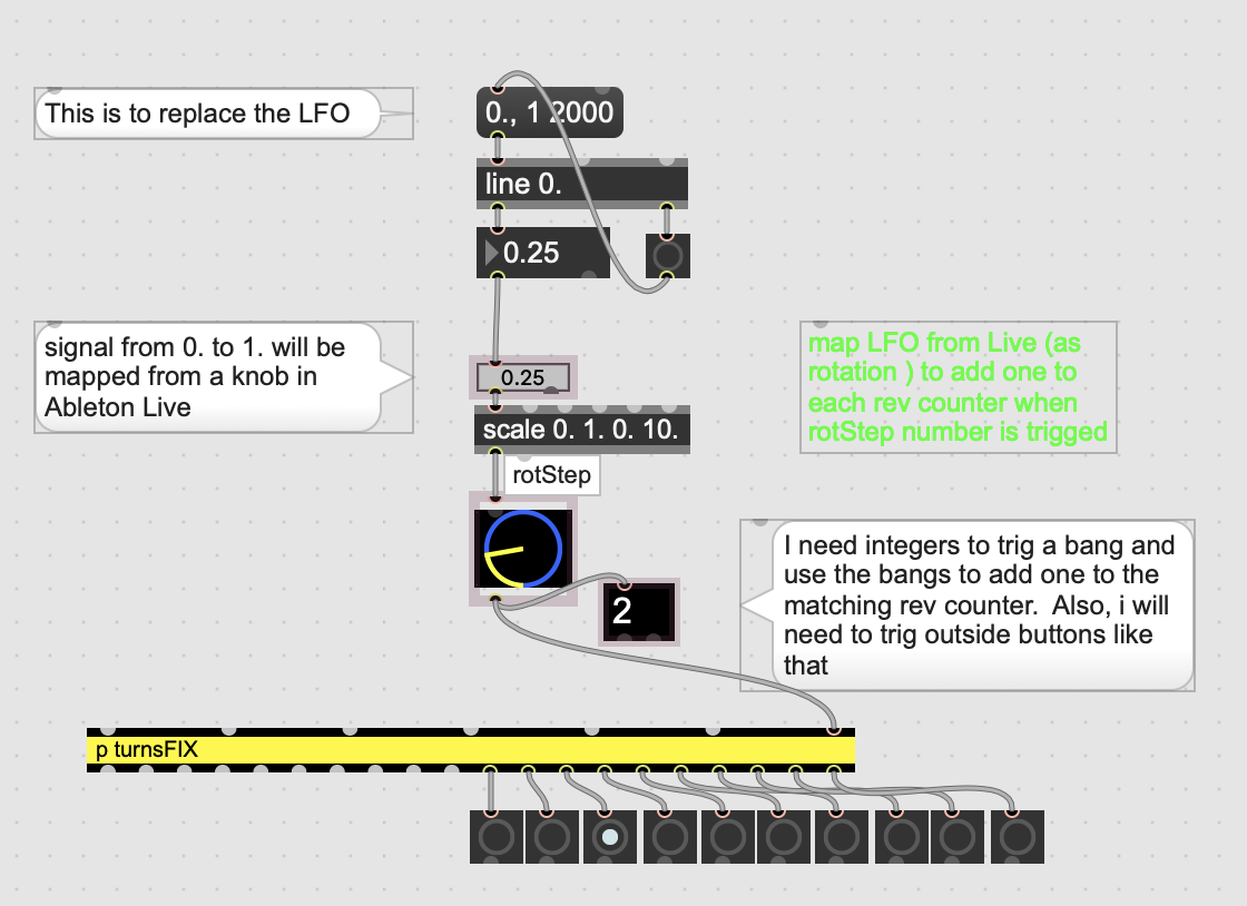
As you implicitly said, we need to have functionality to trigger the cw/cww button if "rotstep" turns to cw/cww.
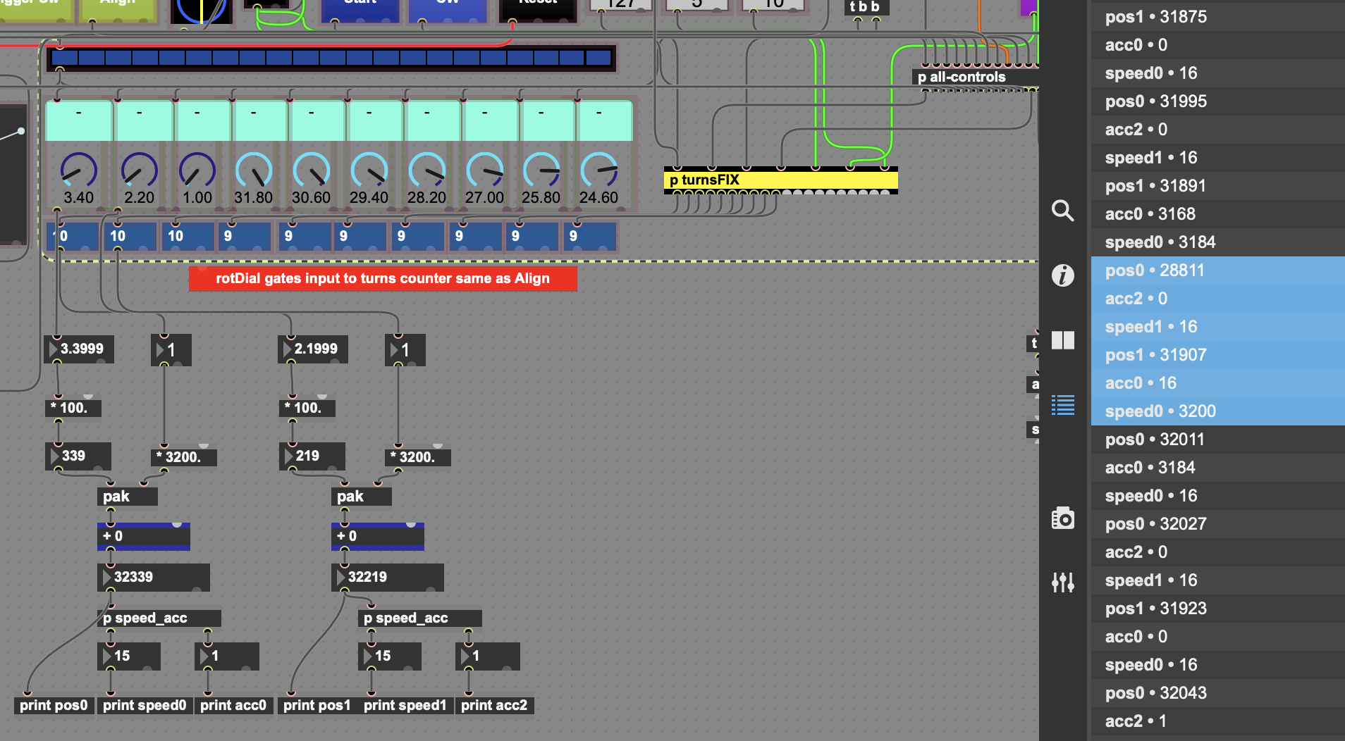
But the important thing I would like to fix is the manner to compute the position of the motor.
I tried in the last patch you have just made VIGER FIX 8jan2025b.maxpat
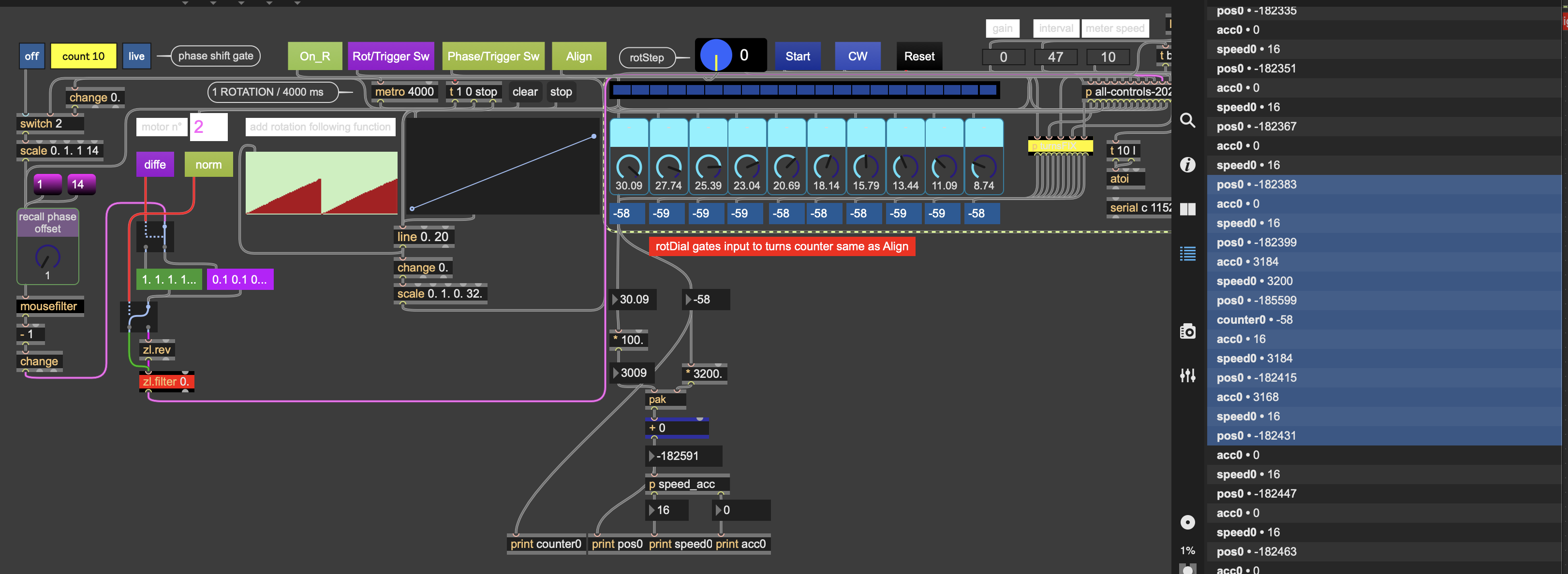
I would like to fix the bug, that I think, comes from the rev counter. As you can see highlihted in blue, positions are 182399, 185599, 182415.
The middle one is not good.
ps : how did you transform coll list to umenu ?
I simply dumped coll to prepend append.
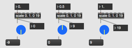
That dial had originally -9 ~ 9 range
do you now want to reduce it to only 0 - 10 ?
to use it's full range you need to scale 0. 1. 0 19
I am afraid I don't understand how do you want to compute real motor position.
Yes . dial had originally -9 ~ 9 range
Now dial is 0 ~ 9 range.
I scale signal from 0. to 1. like that : scale 0. 1. 0. 10.
_________________________
I would like to compute position of my 3200 stepper motor like that.
I multiple * 100 the number of the live dial which is from 0. to 32.
So I have only integer from 0 to 3200.
Then I add the number of rev counter * 3200
So if live dial is 16.52 and rev counter is 2 => 16.52 * 100 + 2 * 3200 = 8 052
the motor has made the 8052 th step.
Ok - I get it about rotation dial.
Will change it in my copy of the patch.
Maybe you have to rethink rotation counter.
truth is that you send all kinds of values
which add, subtract, exchange with different channels etc etc
to a single % 32 modulo at the very end.
rule is a simple one :
~ if CW and current value is lower then previous one - we add 1 count.
~ if CCW and current value is higher then previous one - we subtract 1 count.
Do you want to use that, no matter what you send to that modulo 32 ?
If yes, then rotation counter can be simplified, and take no care
if you rotated list, shifted phases, added whatever.
ONLY respect that 2 values : previous -> current.
You must understand that your system has nothing to do with real rotation,
which must move from point A to point B, not jump.
Ok.
Yes I do with ONLY respect that 2 values : previous -> current..
Thanks ;)
That is not the case now .
test this
rotate dial

Good.
I will use this method for a specific use.
Now it should great to have a default use of rev counter.
We have to add a feature that automatically discriminate the way of rotation dial .
If it is CW and dial rotate respectively from 16.~ 31.99 to 0 ~ 16, then counter incremente 1.
Or it is CW and dial rotate respectively from 0 ~ 16 to 31.99 ~ 16 then counter decremente 1.
Now you see what I mean
Either use real deal or cheat…
What do you mean with specific use ?
But what I really want to know:
Are you driving any motors with this at all ?
Why don‘t you use 360. degrees dial
and center it at top = 0 ?
instad of 32 ?
I think I will use this method for a specific use when I will rotate data with [zl.rot]
But I don't know really how I will do for the moment.
Yes I drive motor with an Arduino, a Teensy actually.
I need to modulate speed and acceleration.
That's why, for today, I really need to get real position.
So if I can automatically set cw or cww, it will work fine.
Yes we can use 360. degrees dial and center it at top = 0
Then I will have to scale live dial like that
[scale 0. 360. 0 3200]
If you use real motors then you can‘t
jump arround with values.
If you have a motor placed at 120
degrees and want to move it to
330 degrees , you have to decide
to rotate it CW 210 or CCW 150
Yes. This is the thing I have had to decide for a long time. But for now, I'm going to use your patch that you just made to calculate the position.
This system is functional because for the moment my motors go only in CW or CWW.
For another use, another rev counting system can be developed. We could calculate the two absolute distances between the new position and the previous position.
Then we will always use the smallest value
We have a motor placed at 120° to move to 330°
Here it is 210° and 150°
We will therefore use 150°
In this case we will go counterclockwise.
In another example
If we were at 330 and we have to go to 120°
the calculation of the distance is still 210° and 150°
We use 150°
In this case we will go clockwise.
In another example
If we were at 10° and we have to go to 160°
the calculation of the distance is still 150° and 210°
We use 150°
In this case we will go clockwise.
I think I will adapt movement of dial in order to move less than 180°/step.
I thought from the beginning that you abandoned motors and use the dials
just for some visual effects. Because one can't run motors synced to dials
using that jumping values.
What are the motors and how do you control them ?
You can jump in software to whatever value/position,
but motor takes some time to reach it also
respecting CW or CCW direction.
For me, that rotation counter is simply useless.
As well as to use it to calculate acceleration or speed.
and there is no need to use 360 float dial,
if you extend it to 36. float. it is easy to scale it at output or in arduino code.
I would replace that live dials with dials with endless rotation
Yes you are totally right.
Could you show me how you incremente position from endless rotation ?
and decremente....
And I will need to multiply rotation *3200 and add position from endless rotation.
Could you do it please ?
I use your method to count revolution in the last patch you have made.
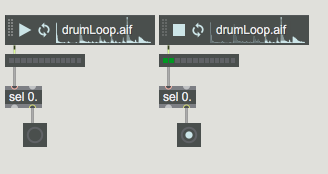
it works fine. I keep this method for today because I have to make a video of my installation today. Below the test with the first live dial
But it 's not what you have just said this morning
I am really willing to help you, but simply don't know how.
what are you trying to do ?
Do you want to sync a motor position with dial position ?
Rotation count makes no sense unless you want to
calculate total travel of a wheel.
like with a car : wheel with 50 cm diameter has one rotation length of 157 cm.
rotate it 10 times + 30 degrees = 1583 cm.
but that is not what you need , or ?
Forget this rotation counter.
It makes no sense.
Hello,
Yes I want to sync a motor position with dial position!
I think we just have to add or subtract the number of steps, to the previous position to control the motors.
If we are in CW then positionMotor=positionMotor+positionDial
If we are in CWW then positionMotor=positionMotor-positionDial
Indeed, we don't need rev counter anymore!
Below I explain how the motor should react:
Let's say that the movement between the current position and the previous position is always less than 180°.
If the dial goes from 120° to 180°, the motor will do 60 * 3200 / 360° = 533.333.
so it will have to do 533 steps clockwise.
Then, if the dial goes to 180° at 1°, the motor will do 179 * 3200 / 360° = 1591.11
so it will have to do 1591 steps counterclockwise.
Finally, if the dial goes from 1° to 182°, we choose the shortest path, which is 179°.
because the two calculations of the angular distance are
182-1= 181°
1-182+360 = 179°
So the motor will make 1591 steps counterclockwise.
I would like the motors to be as responsive as possible. I want, if possible, the speed and acceleration to be proportional to the distance traveled (the number of steps).
Thank you very much
In case you want to have dials and motors synced,
I think you have to go from motor specs and translate that to
controls in live that motor can follow reliably.
What speed motor can do in what time ?
when you say we don't need rev counter , you mean rotation counter all together ?
If you now wan't to do this all properly, what about CW/CCW switch ?

now all has to be translated to 360° instead of 0. - 32 float.
then, maximum change must be less than 180°
what libs do you use to run which motors ?
why 3200 steps ?
if it is a step motor than it has specs.
usually 200 steps per full turn, or 1.8° per step.
Post them, as well as arduino code.
live dials can move as fast as possible, motor not.
to run stepper motor one has to defins direction, speed
number of step to go etc etc.
Motors themself would react so or so depending on weigth they have to move ...
so many factors.
And you have to reset motor position to be able to tell it to go somewhere
that equals dial position.
The motors I have are Nema 23 which are 1.8° for 200 steps.
The holding torque is 1.2 N.m
I divide the step size by 16 thanks to my good digital drivers.
So I have 3200 steps and a precision of 1.8/16 = 0.113 degrees per step
This way the motors are driven silently and without tremors
I think counting revolutions is no longer useful if you add or subtract the engine positions from the previous positions.
On the other hand, I want to be able to control the directions of global rotation, so we keep the current configuration of the patch with CW and CWW
For the Arduino part,
There is no need to control the direction of rotation with my digital drivers
I use the acceleStepper library
You can modulate the speed and acceleration
I rotate a 30 gram aluminum bar on which I attached an 8*32 LED strip
I also have a small box with a fairly heavy battery (the same as for electric cigarettes) which I fixed on the aluminum bar as close as possible to the axis of rotation of the motor.
In total I'm running something weighing 120 grams.
So, absolutely no sudden movement is necessary.
I can get the motors to run at two revolutions/sec
A maximum acceleration of 1 revolution/sec seems more than sufficient to me.
Here the Arduino code
#include <AccelStepper.h> // Define a stepper and the pins it will use
#define NBMOTEURS 10
#define NBDATA 34
#define NBPASPARTOUR 3200 // numberOfStep/round

long ABC[NBDATA] = {0,0,0,0,0,0,0,0,0,0,0,0,0,0,0,0,0,0,0,0,0,0,0,0,0,0,0,0,0,0,0,0,0,0}; // Teensy has to parse 34 ints fromMaxForLive
//position == data from 0 to 9
//speed == data from 10 to 19
//acceleration == data from 20 to 29
//other data from Max4Live == data from 30 to 33

#define STEP 1//. set driver to subdivise step.
// 800-->Mode 1/4 pas MS2 sur ON
// 1600-->Mode 1/8 MS1+ MS2 sur ON
// 3200--> Mode 1/16 MS3 sur ON
// 6400--> Mode 1/32 MS1+ MS3 sur ON

//  Teensy (better than Arduino)
 const uint8_t PINDIRECTION[NBMOTEURS] = {6, 9, 12, 26, 29, 32, 34, 37, 39, 41 };
 const uint8_t PINSPEED[NBMOTEURS]=      {5, 8, 11, 25, 28, 31, 33, 36, 38, 40 };
 const uint8_t ENABLEPIN[NBMOTEURS]=     {4, 7, 10, 24, 27, 30, 133, 135, 139, 142};

// Define a stepper and the pins it will use
AccelStepper stepper[ NBMOTEURS] = {
AccelStepper (STEP, PINSPEED[0], PINDIRECTION[0]),
AccelStepper (STEP, PINSPEED[1], PINDIRECTION[1]),
AccelStepper (STEP, PINSPEED[2], PINDIRECTION[2]),
AccelStepper (STEP, PINSPEED[3], PINDIRECTION[3]),
AccelStepper (STEP, PINSPEED[4], PINDIRECTION[4]),
AccelStepper (STEP, PINSPEED[5], PINDIRECTION[5]),
AccelStepper (STEP, PINSPEED[6], PINDIRECTION[6]),
AccelStepper (STEP, PINSPEED[7], PINDIRECTION[7]),
AccelStepper (STEP, PINSPEED[8], PINDIRECTION[8]),
AccelStepper (STEP, PINSPEED[9], PINDIRECTION[9]),
};

//   Receive with start- and end-markers combined with parsing
const byte numChars = 200;
char receivedChars[numChars];
char tempChars[numChars];        // temporary array for use when parsing

    // variables to hold the parsed data
char messageFromPC[numChars] = {0}; //or 5 doesn't change anything

int enableDriver1= 0; // test enable driver. I don't need but I wanted to test
int led = 13;
boolean newData = false;

 // CHECK NUMBER OF ROUND AND GOOD MOVEMENT

int testOneRevolution;

void setup() {

    Serial.begin (115200);

 for(uint8_t i = 0; i < NBMOTEURS; i++) {
  stepper[i].setMinPulseWidth(5); //****************************************if TEENSY's clock is very fast, motor needs a little pulse

    // Initialisation des pins moteurs
    pinMode(ENABLEPIN[i], OUTPUT);
    digitalWrite(ENABLEPIN[i], OUTPUT);
    digitalWrite(ENABLEPIN[i], LOW);

    pinMode(PINDIRECTION[i], OUTPUT);
    digitalWrite(PINDIRECTION[i], OUTPUT);
    pinMode(PINSPEED[i], OUTPUT);
    digitalWrite(PINSPEED[i], OUTPUT);

   stepper[i].setMaxSpeed(NBPASPARTOUR*2); // 6400 step*sec^-1
     }

  testOneRevolution=NBPASPARTOUR;

  ABC[NBDATA-2] =1; // ratioSpeed. // maybe I will use
  ABC[NBDATA-1] =2; // ratioAcc // // maybe I will use
  enableDriver1 =1; // enable driver 1 // just to test

 for (int i =0; i<NBMOTEURS; i++) // setPositionToMotor
   {
       ABC[i]=testOneRevolution;  //
       stepper[i].moveTo(ABC[i]);
       stepper[i].run();
    }

 for (int i =NBMOTEURS; i<NBMOTEURS+10; i++) //setSpeedToMotor
   {
       ABC[i]=600;
       Serial.print( "  speed " + (i)); Serial.println(ABC[i] );
    }
 for (int i =NBMOTEURS+10; i<NBMOTEURS+20; i++) //setAccToMotor
   {
       ABC[i]=300;
       Serial.print( "  acc " + (i)); Serial.println(ABC[i] );
    }

Serial.print( " SPEED "); Serial.println(600_steps_made_in_one_sec);
   }

void loop() {

 for(uint8_t i = 0; i < NBMOTEURS; i++) {
    stepper[i].setMaxSpeed(ABC[i+10]);  // speed is set from Max
    stepper[i].setAcceleration(ABC[i+20]);  //acceleration is set from Max

    //SPEED MAX
     if (  3200+ (1 * ABC[i+10] *1.0*ABC[NBDATA-2])>= NBPASPARTOUR*2)
      {
      stepper[i].setMaxSpeed(NBPASPARTOUR*2);
      }

   }
   recvWithStartEndMarkers(); // receive data like that <10,258,.....,-32> //  then split them
    if (newData == true) {
        strcpy(tempChars, receivedChars);
            // this temporary copy is necessary to protect the original data
            //   because strtok() used in parseData() replaces the commas with \0
        parseData();
        newData = false;
    }

     moveMotorSetOneByOne();  // i control motor differently because they are not linked to the driver in the same "way of rotation"
  }

void recvWithStartEndMarkers() {
    static boolean recvInProgress = false;
    static byte ndx = 0;
    char startMarker = '<';
    char endMarker = '>';
    char rc;

    while (Serial.available() > 0 && newData == false) {
        rc = Serial.read();

        if (recvInProgress == true) {
            if (rc != endMarker) {
                receivedChars[ndx] = rc;
                ndx++;
                if (ndx >= numChars) {
                    ndx = numChars - 1;
                }
            }
            else {
                receivedChars[ndx] = '\0'; // terminate the string
                recvInProgress = false;
                ndx = 0;
                newData = true;
            }
        }

        else if (rc == startMarker) {
            recvInProgress = true;
        }
    }
}

//================================================================= RECEIVE 34 DATAS FROM MAX_FOR_LIVE

void parseData() {      // split the data into its parts

    char * strtokIndx; // this is used by strtok() as an index
    strtokIndx = strtok(tempChars,",");      // get the first part - the string

    for(uint8_t i = 0; i < NBDATA; i++) {
    ABC[i] = atoi(strtokIndx);     // convert this part to an integer
    strtokIndx = strtok(NULL, ","); // this continues where the previous call left off
    }
    }

void moveMotorSetOneByOne(). // sometimes there is -ABC[9] or  ABC[7]... because my motors are not plugged in the same rotation way.
 {
       stepper[9].moveTo(-ABC[9]);
       stepper[9].run();

       stepper[8].moveTo(-ABC[8]);
       stepper[8].run();

       stepper[7].moveTo(ABC[7]);
       stepper[7].run();

       stepper[6].moveTo(ABC[6]);
       stepper[6].run();

       stepper[5].moveTo(ABC[5]);
       stepper[5].run();

       stepper[4].moveTo(-ABC[4]);
       stepper[4].run();

       stepper[3].moveTo(-ABC[3]);
       stepper[3].run();

       stepper[2].moveTo(-ABC[2]);
       stepper[2].run();

       stepper[1].moveTo(-ABC[1]);
       stepper[1].run();

       stepper[0].moveTo(ABC[0]); //
       stepper[0].run();
}
Well it is your decision how to drive motors, but think that
you are allways reacting to what value a dial has.
motor will need some time to get where dial is
using your complicated control
which is more suitable to run motors alone
then to chase external absolute position.
that will definitelly put motors out of sync quite soon.
two revolutions/sec meany maximum 120 RPM.
your patch produces much faster movements.
did you consider using
mystepper.moveTo(targetPosition);
....
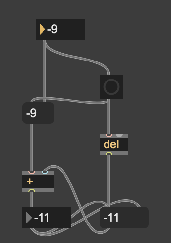
I would have constructed all this a bit different,
use phasor~ to rotate using speed derivated from audio level,
and to create that offsets and what you call phase shifts
use delayed output.
every time you align or rotate the list,
jump arround, pause the process , position the list, continue.
And all of that respecting motor capabillities.
in this case 120 RPM
mystepper.moveTo(targetPosition);
what is the difference with stepper[9].moveTo(-ABC[9]); ?
-ABC[9] is the target position.
You mean, I have to send position continually with data from [phasor~]. With this object I will can compute speed more easily ?
Can you show me a patch please to control two motors? with delayed output and all the processes you pointed out.
Ha, ha that would be a good deal of work.
I mean not to run phasor, but to play this game with rotations,
offsets etc.
That are the problems.
I will soon post example using phasor to drive dial/motor using audio level.
a very simple starter
it looks perfect! I hope it will be easy to add the others features. Sound and mouvement will be as a maximum tuned.
I'm very happy ;)
Ah, ok, now please think about max speed your motors should move.
I think man thing now is to decide which objects
to use in signal and which in non signal domain
to play with 10 motors offset , speed etc.
You must insert change 0. and speedlimit at end to tame
serial data flow and motor position refresh rate.
if I understand correctly you don't need to send anything else but position - list of 10 floats.
you can simplify arduino code quite a bit.
you said You must insert change 0. and speedlimit at end to tame
you speak about the last patch you made ?
I need to send speed and acceleration if I want to control motors as smooth as possible.
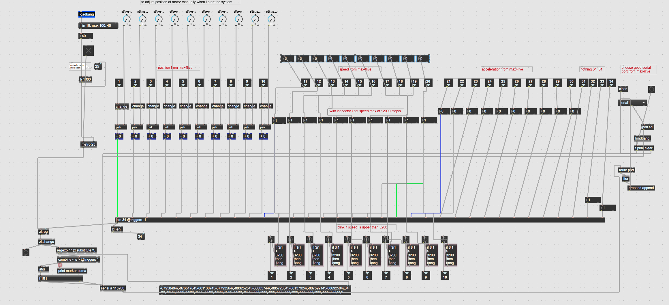
Here the patch to send data to Arduino.
I added [change]. because we will send integers
You can see that adjust motor manually (because I don't have encoder to automatically align motor)
I adapt a patch you have made for me.
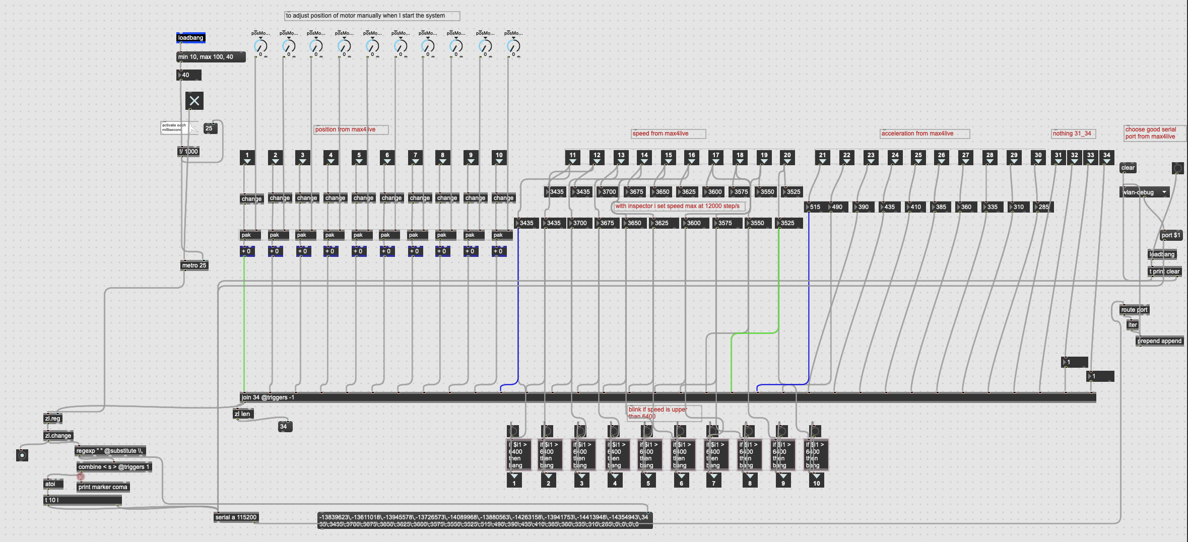
Last patch had that after one dial only - the one that could rotate phase.
I see - you allways send full list instead of individual sliders,
similar as DMX, collect the list,
but bang it at acceptable interval ... all ok.
Ok. ;)
Will you be able to add all the options (rotation, phase shift gate, etc.)? because I'm not sure I know how to do it well.
And a quick question how do we add a position to the previous one. like the += operation?
like that ?
No, sorry.
the difference to previous patch is that dials do not jump but run by phasor speed.
in older patch you were jumping because of all that rotations shifts etc.
what do you want to do now to that phasor ?
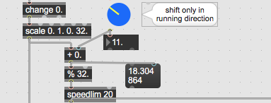
offset between 10 channels is easy, run phaser through +~ and %
as I posted - shift only in running direction if you
want rotation counters to work.
If you again want to use all that stuff from old patchers,
then do it , but I am out of that.
I will try to explain again what makes it difficult for me
to help you.
motors are mechanical things and you can not expect them to
follow construct like in your previous patches.
not if you need them synced with dials.
one comparison :
if you have 2 people walking same tempo and step length
synchronised and you suddenly want one to be 2 meters in front of the other,
one has to either jump 2 meters to be able to march in same tempo again.
or you have the other guy to pause till that distance is achieved.
but they have to march synced again left, right, left, right in same tempo and step size again.
Same thing is with your motors which have limit of 120 RPM,
means 2 turns / second maximum.
Your speed could allready be quite high due to audio level,
and then you suddently punch half turn on top of it
because you added from one of several sources,
or you even rotated the list.
Whatever effects you want to create now if you use phasor~
for rotation, go from motor control in first place,
then look for effects in the range of possible movements.
either pause till you reposition motors - which is against
main task - MOVE REACTING TO AUDIO LEVEL.
Or scale speed over 10 motors list, or I don't know what else.
but not large JUMPS while rotating,
also not in oposite direction if CW / CCW have any meanning.
You said
Or scale speed over 10 motors list, or I don't know what else.
but not large JUMPS while rotating,
It 's exactly what I'm going to test tomorrow.
That's why I wanted to adapt speed with the movement.
If I add a phase offset, it will make a jump while rotating.
Speed will be up just a few moment.
I add knobs in order to have a minimum speed and acceleration.
Maye be I will have to multiply speed or acc and see how motors will react.
I do not know exact specs of the motors,
but if you say max 120 RPM, it is better to stay under that.
problem is - accumulated speed : running + whatever added.
Understood
just to tell I have a fixed a bug, but maybe I don't respect a good procedure.
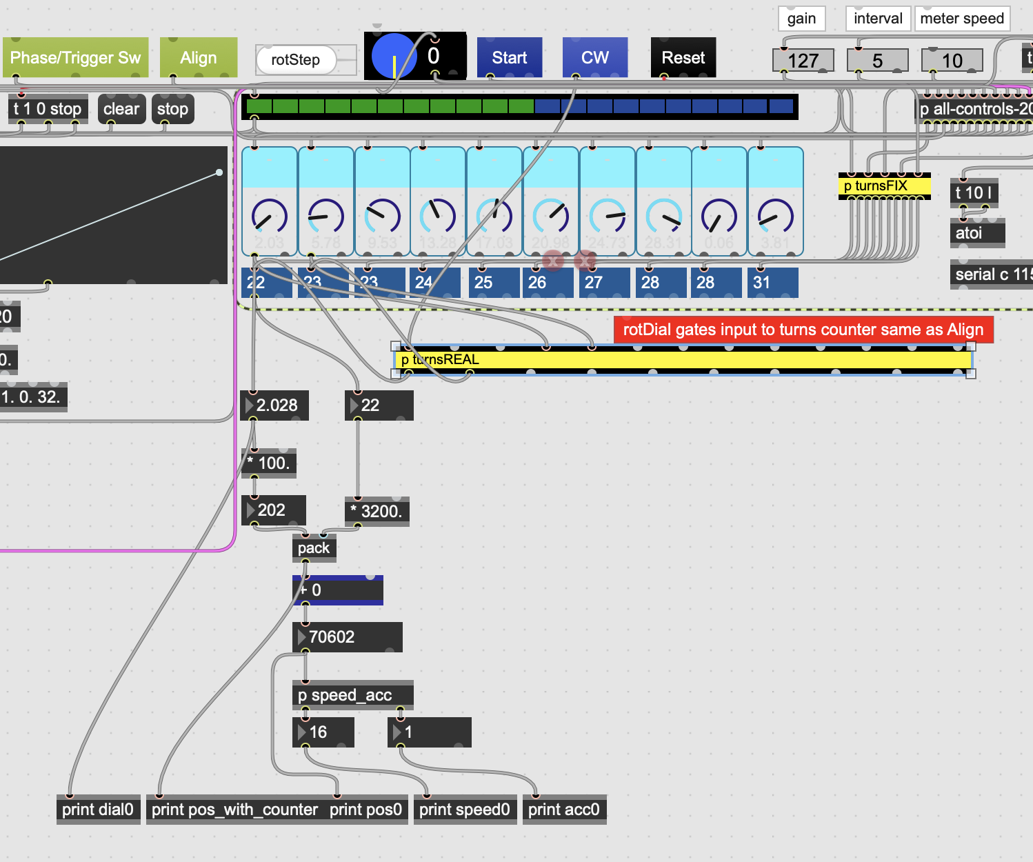
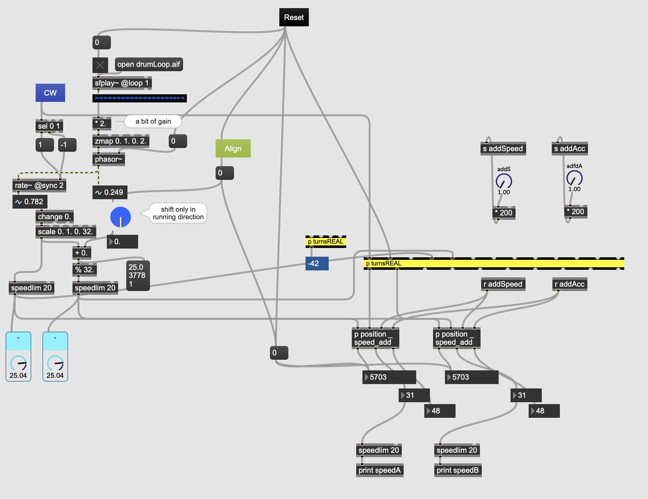
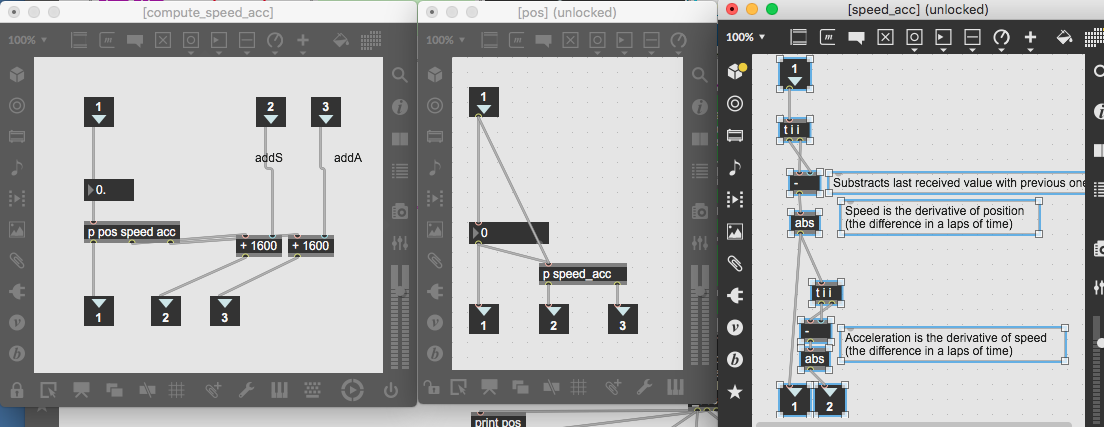
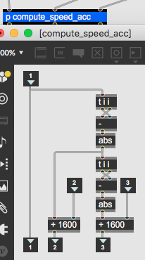
I added [p turnsReal] to the last patch you made on JAN 8, 2025 AT 3:53 PM
and I added [p position_speed_add] the same as you can see just above.
By doing a simple rotation to all dials,
I have seen a bug by computing position. But only for the three last dial. There is a bug for speed and acceleration too.
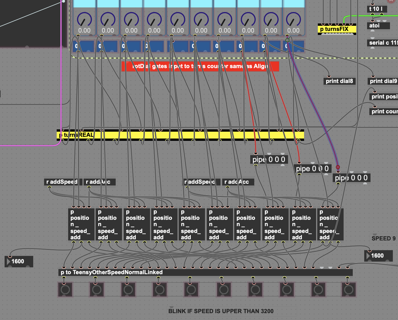
The datas of
dial9, dial 8, dial 7, "comes too early" in comparison with the number of turn in the [p position_speed_add].
That why I added [pipeline] between each live.dial and [p position_speed_add].
The links are in red.
If you link dial9, dial 8, dial 7 as the others one, you will see speed > 3200 when dial is making a new turn. That's mean there is a bug.
ps: I will use [phasor~] when I will have time and If a see a big difference by controlling motors.
That new rotation can not work with your old patch.
No way.
It is meant for rotation that does not change direction.
maybe you can fix that by limiting changes to less than half turn
maximum.
And that no matter where from that change comes.
Including rotation of the list.
Hello again
I used the new method to compute position and all motors works as they should. Thanks so much !
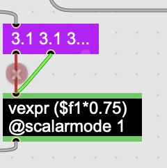
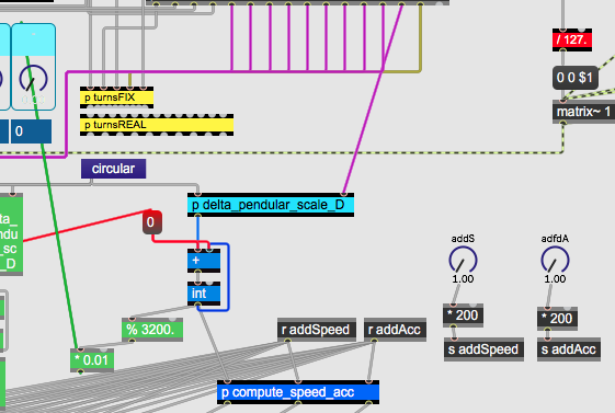
In order not to have a step greater than 16, I had to modify the phase shift amplitude by multiplying by 0.75. As you can see with [vexpr ($f1*0.75) @scalarmode 1]
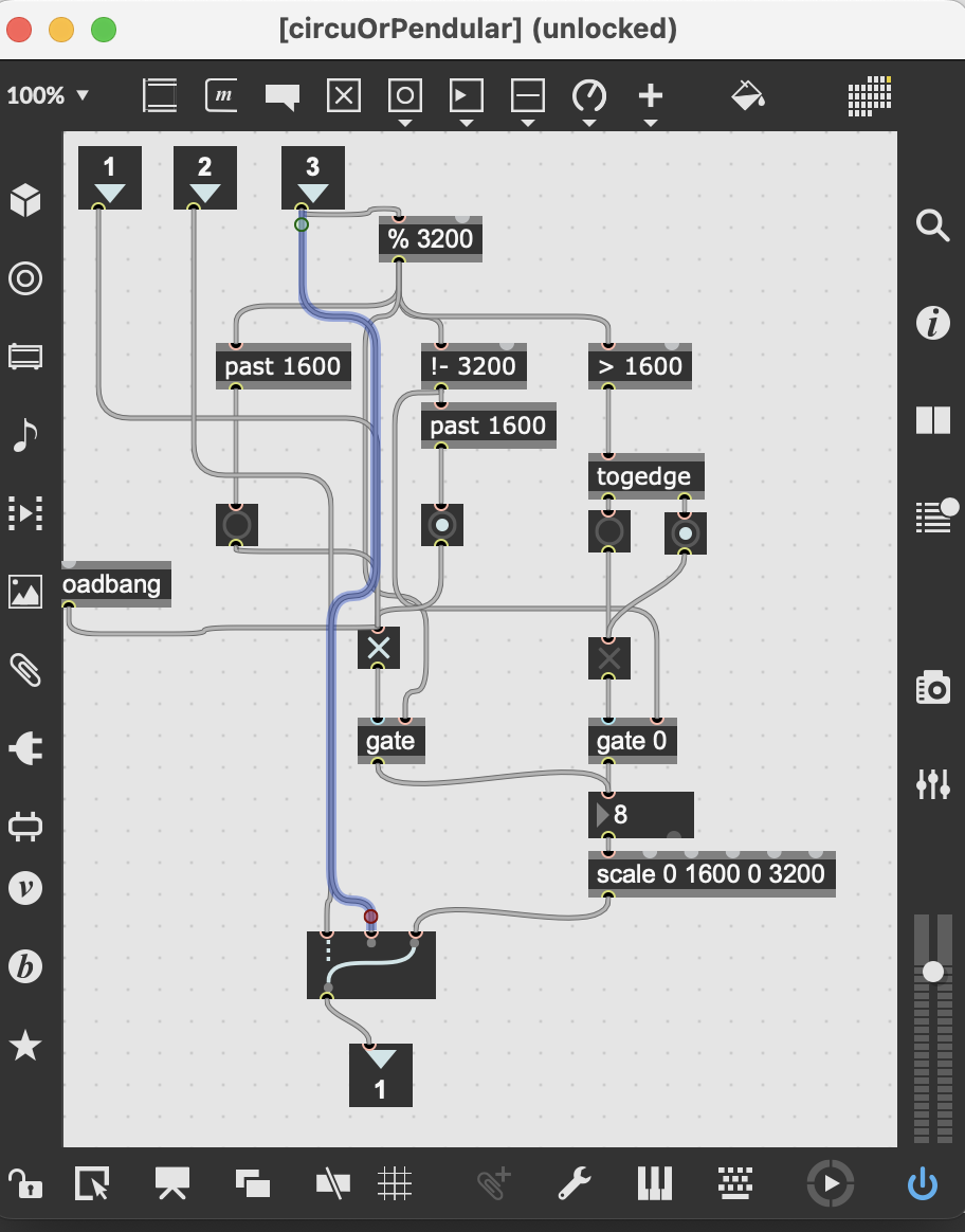
I added a feature to transform rotation (circular motion) into pendulum motion
I added it just before the method to calculate the position.
I print position and speed of dial 0 and it seems to be good.
It should work .
Could you tell me, please, if the method to transform the movement from circular to pendular is well appropriated ?
your patchers allways get in this form, who is routing all that patchcords ?
It makes it very difficult to follow what is connected where .
remove all leftovers before uploading stuff
one needs to open all this in order to see if it makes sense
instead of having it like this
I am not really able to see this without zooming out in my 2560 > 1440 screen
only to send 34 values to teensy ?
what I want to point is that I need to spend much time to reshape your patches
in order to try to help you, and sometimes I simply have no patience and time to do so...
Understood, I'm sorry, I believed I made some improvements but I still have to be more rigorous.
I have just changed option to get "segmented patch chord", I will make straight oblique lines.
I found the first patch on this forum and I didn't change the patch chords.
I added scale [0 1600 0 3200] to make the pendulum movement with an higher amplitude
I wonder If it was well appropriated to scale the movement here ?
Due to a phase shifting we make to a rotation movement , with pink dial "recall phase offset",
I think the phase offset to a pendulum movement will be strange
But when I look at speeds and positions, all seem to be all right.
I have to test this patch with my motors to see If there is an erratic movement.
ps : in the last patch you saw I made a little bugs
Thanks a lot Teatcher.
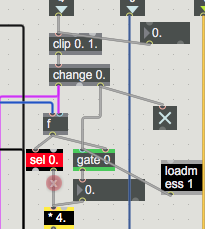
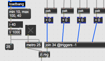
what is purpose of this 2 loadbangs ?
to toggle gate opposite from what ?
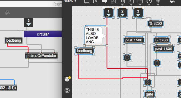
and that important gates are ONLY controlled by bangs.
Which produce no definite state ?!?
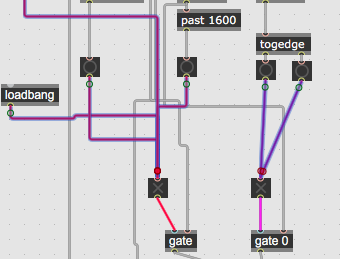
can you not fix that and insert 0 and 1 instead ?
output from all-control patcher is run through % 32.
you multiply that with 100.
why is % 3200 needed here ?
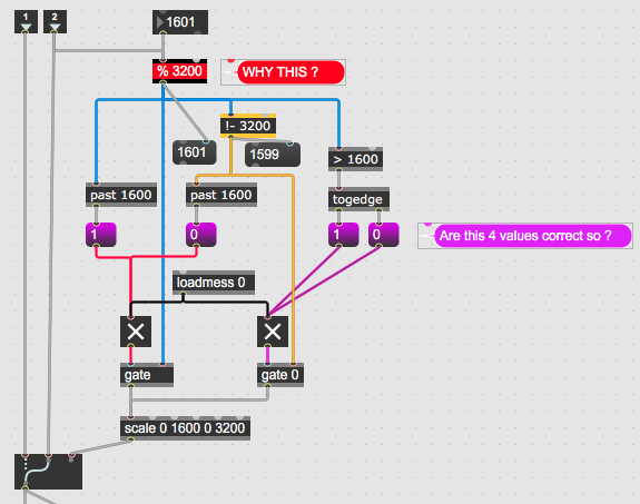
I'm changing my answer because I didn't see your last post.
% 3200 is useless, indeed.
I can't tell you what the right values could be.
But I'm sure the two gates can't be in the same state.
So [gate] and [gate 0 ] must be either 0 1 or 1 0
I had cleaned the patch like that before seeing your
= > I removed the two bang to pre-boot the patch. There were useless actually
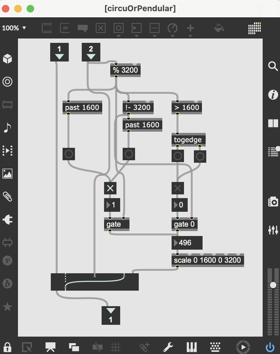
When you launch rotation with button ON_R and Rot/Trigger Sw, all dial will rotate
When you trig on pendular you will see the pendular movement.

Here the entire patch
To be able to help if needed,
I need to know what should that pendulum patch do.
Just playing lottery with bangs - i have no time for that.
To test, one woud input straight numbers
one after another and see where it goes,
but can you not tell in simple words what should it do ?
I mean if input changed more then 1600 then ... and so on.
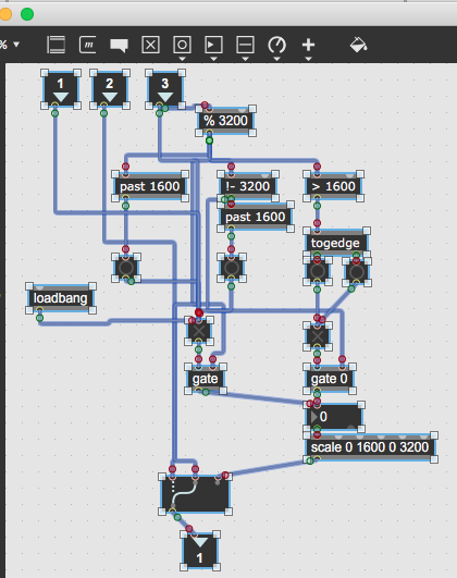
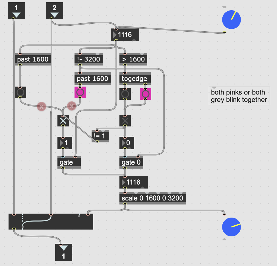
here is test patch for you to see what it does or should do
and check what that 4 values that control gates should be:
if you enter 0, and after that 17 all gates get high...
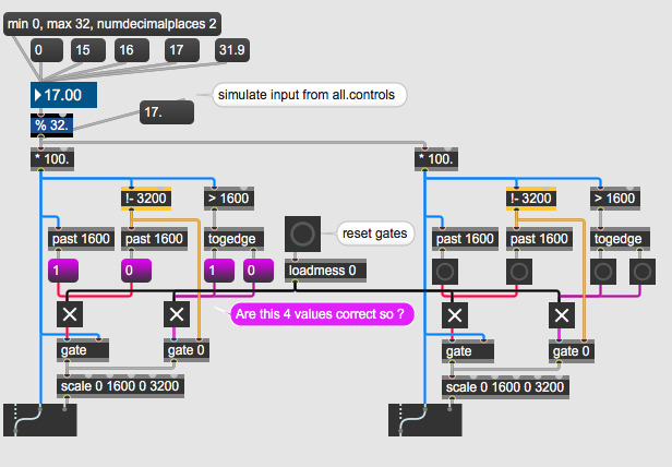
.............................
Now I see you don't count turns, and dials are only following what gets output to motors,
but not really because you again add that 2 values speed/accel on top of that
what shoud limit to 12000 do ?
another question:
if your motors have max speed of 2Hz (2 full rotations per second)
and you send that list to teensy 40 times per second (40 frames or 25ms interval),
what is maximum travel that can be done by motors in 25 ms interval ?
Can they manage to jump that fast if you rotate the list ?
With your questions, I have found solutions.
I will tell you tonight. Thanks
Here a small answer.
I trig always an opposite value on each gate thanks to [!= 1]
If you rotate the dial on top, you will see what the movement should be an the other
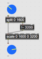
if that is what you want, then this is all it needs :
Dear Professor,
The apparent simplicity of the method in your last post completely surprised me, and I forgot to thank you.
Thank you very much.
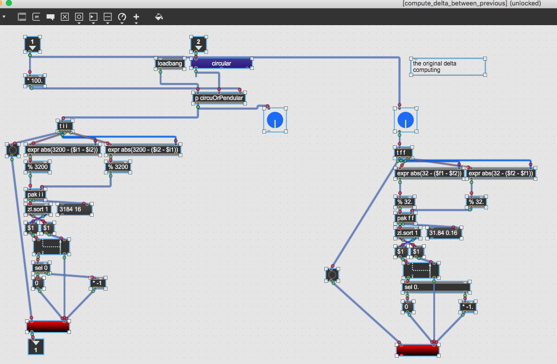
I created a green patch "delta_pendular_circular using your method to switch from pendular to circular motion.
_______________________
Now, I would like to be able to automatically adapt the speed and acceleration of each motor when the motion is pendular (and later for circular motions)
The maximum speed of a pendulum motion I tested is from 0 to 1600 in 500 ms, then from 1600 to 0 in 500 ms.
I send the position 1600, then 500 ms after sending the position 0. It works. I set the motor to a maximum speed of 12,600 steps*s-1 and a maximum acceleration of 2,400 steps*s-2.
I can set a higher maximum speed, but it doesn't change the pendulum motion.
If the acceleration is higher than 2,400, my motor won't follow the motion due to the load it's carrying.
Let's assume the motion is as shown below and each position is sent every 25 ms.
From 0 to 1300 at 25 ms, then no movement for 400 ms, then after 1300 to 1600, from 425 to 450 ms, then no movement thereafter.
If I calculate the speed (steps/s) every 25 ms, I get:
1300/ 0.025 = 52000
0/0.025 = 0
0/0.025 = 0.....
The speed is always 0, then at the 425th second,
200/ 0.025 = 8000
0/ 0.025 = 0
I can't calculate the speed as 52000, then 0, because if I do that, my motor would stop after 25 ms when it would actually take 406.25 ms to start and stop at 1300 step
As a reminder, the motor can reach 1600 in 500 ms maximum, if we start at 0 and stop at 1600, then change the direction of rotation.
Should I interpolate the position to better follow the actual movement of the motor?
Should I calculate the speed differently?
The goal is to have an approximation of the actual movement and to calculate the velocity and acceleration in order to obtain a smooth and fluid movement.
Thank you, I have no idea how to do this.
I have no time at the moment to dive into new patch,
but will do so as soon as I get time.
I think you made a wrong calculation.
If you want to travel from 0 . 1300 within 25 ms,
then divide 25 / 1300
but this looks wrong again, thinking of speed limit.
What is it exactly ?
I mean single step speed ?
when you have that , multipy that by travel distance.
you wrote :
"The maximum speed of a pendulum motion I tested is from 0 to 1600 in 500 ms, then from 1600 to 0 in 500 ms."
That would mean 500 ms / 1600 steps = 0.312 ms per step
0 - 1300 = 1300 * 0.312 = 406.25 ms
Hi,
Thanks for helping ;)
I don't really understand why you calculate speed as ms/step.
I have to control my stepper motor by changing the speed and acceleration in step/s and in step/s/s
In the Arduino I can set maximum speed and maximum acceleration
stepper[i].setMaxSpeed(ABC[i+10]);  // speed is set from Max
stepper[i].setAcceleration(ABC[i+20]);  //acceleration is set from Max
I send position, speed and acceleration each 25 ms to the Arduino.
The motor can move from 0 to 1600 in 500 ms . (an half turn in 500 ms)
To do this It needs a very high acceleration and a speed set to a minimum of
3200 step/s because 1000 ms/500ms * 1600 =3 200
But to start at 0, to move to 1600, to stop to 1600 and go back to 0
motor needs a speed higher than 3200 step/s . ( at the beginning and the end of the movement)
I don't really remember how I set speed max, maybe 6400 step/s to see the pendular movement
0 ->1600-> 0
I tested acceleration max, I can't go up that 2400step/s/s
So I was wondering how to control a motor whose movement isn't as simple as:
Move to 1,600, then 500 ms later, return to 0 with maximum speed and acceleration set to 6,400 and 2,400.
For example, if we start at 0, then the next position sent 25 ms later is 1,300. I know it's impossible for the motor to move 1,300 in 25 ms. Because to take 1,300 steps, we need 1,300/3,200 = 406.25 ms.
My question is
How do I calculate the positions, velocities, and accelerations to send to the Arduino so that the motor operates according to its likely movement?
Should I break down a sudden movement into several shorter movements?
Or is it possible to calculate speed and acceleration automatically by keeping position even if the positions are not possible ?
How could we compute acceleration and speed of this movement ?
From 0 to 1300 at 25 ms, then no movement for 400 ms, then after 1300 to 1600, from 425 to 450 ms, then no movement thereafter.
follow motor limits, that's it.
You decided to use that speed/accel stuff, instead of
simple positioning, to send motor to absolute position.
Now you have to live with that.