building circuits using gen~
Hello!
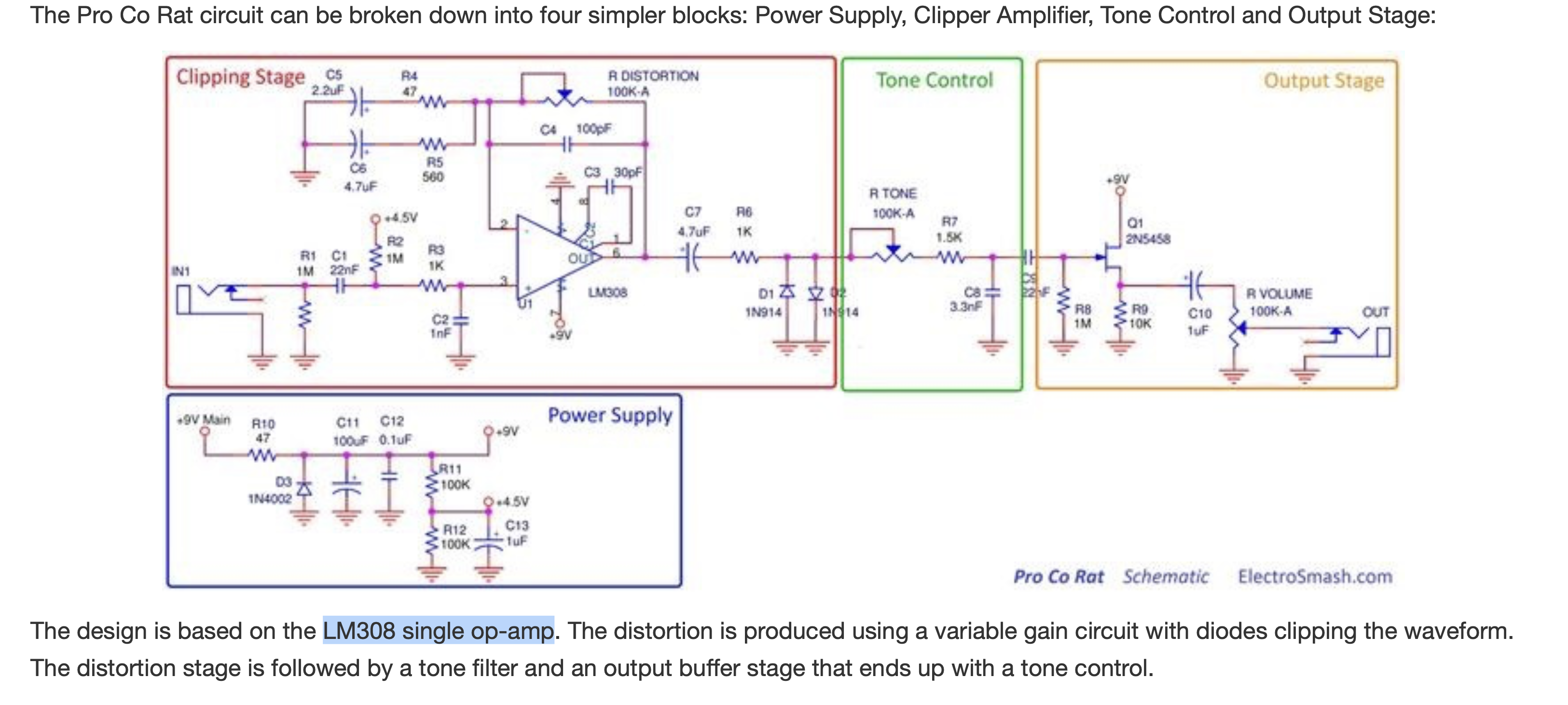
I'm a computer music major and I really need a project to present to juries this semester, I was thinking it could be cool to try and follow circuit diagrams for pedals in Gen~ namely a Rat distortion pedal. I found the circuit diagram online, I'm just struggling to try and formulate it in Max. Is there any approaches?
I like this task cause I used Rat wayyyyyy back in the day.....

Modeling analog to digital though...
I'm not sure how familiar you are with both analog circuit physics and gen~ patching, but modeling analog circuits in general can get quite hairy.
An individual RC filter for example can be approximated relatively easily with a one pole filter (and to make it a bit more accurate, using a trapezoidal one pole) -- I think that's more-or-less what the Tone Control section up there is, from a quick glance.
But the interaction of many components can be a lot less straightforward, especially when there are nonlinear effects going on (and I assume the clipping stage of the RAT has quite some nonlinearities!)
Part of this comes down to the fact that in the computer, data flows in one direction only, but in an analog circuit the relationships of current, voltage, impedance etc. between components are mostly bidirectional. That's partly why circuit modelers involve solving multiple parallel differential equations.
Even things like Falstad, KiCad etc., which are pretty powerful circuit simulators, struggle to model some popular audio circuits. I believe that modeling the extreme limits of opamps is one of those cases, and I wonder if the RAT is using that kind of behaviour.
Maybe someone can help decipher some this... especial that "Clipping Stage"
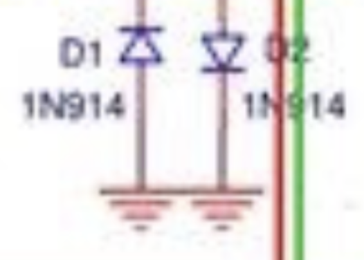
i think most of the clipping stage in that schematic simply works a large amount of amplification and 'compensation'(by way of the LM308 opamp), through the two diodes at the output... as if they perform like a signal 'rectifier', but for both the negative and positive parts of the signal individually:

as Graham mentioned, there's often effects performed when pushing different 'components' into "extreme limits" which are hard to model in the digital realm without additional considerations/math(such as adding 'sigmoid'-style shaping within the path of any digital math that performs 'clipping' in order to achieve a more natural sounding 'saturation' before the hard-clipped portion of the signal is achieved).
there's also the fact that diodes will behave differently with reverse current:
so you can start to imagine that, whatever the diodes do at the end of the signal path within the 'clipping stage', might actually be adding some form of imperfection or imbalance to the way the signal is managed before their output sum(i.e. if they are rectifying the positive part of the signal/AC-voltage differently than they rectify the negative part, the summation will be an interesting mix of those imperfections).
furthermore, it's essential to look at the datasheets for parts listed. here's a datasheet for the LM108/308 opamps, which shows some typical circuits, that may be similar to the circuitry surrounding the same op-amp in the above RAT schematic:
notice there's the different 'compensation' circuits which look similar to what's seen in the rat. but in the schematic for the rat, the 'comp' inputs are connected together with nothing but capacitors in between more like the 'standard compensation' circuit listed in the above datasheet.
so the capacitor labelled C4 at a value of 100pf is likely performing as a 'phase compensation' capacitor:
(the video mentions that the capacitor "also has the effect of suppressing high-frequency noise", but how much that defines the particular tone of the rat may be subjective)... my point being, not everything that deals with the nature of how opamps act on 'negative feedback', will need to be simulated exactly as in a schematic(you might try to put a one-pole lopass in the feedback path, but it will not sound exactly the same).
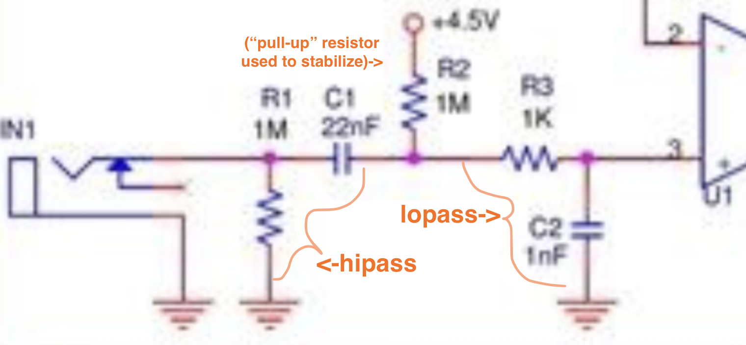
in the RAT schematic, there's also both hipass(around 7Hz) and lopass(i'm not sure of the frequency here, because the pull-up resistor of 1M alters the structure to become more complex), before the 'non-inverting' input of the opamp:

here's another good thread to consider different possibilities in tone for different opamps within similar rat-like schemes:
i can suggest 2 different approaches to this task:
1) get to know details of how this specific opamp(LM308) and all the specific components listed in the schematic work, as well as acquiring an almost electrical-engineering level of knowledge and expertise on every part of the circuit(such as RC networks, voltage dividers, amplification, negative-feedback techniques applied to opamps, etc.), and then proceed in software to model the action on signals in a similar way given what you've learned from that 'electrical-engineering' level of expertise.
2) build the actual analog circuit first, get it to work as you'd expect, and then pull it apart and test the individual modules/parts of the schematic to see what kind of sonic/tonal differences you can achieve when altering the circuit. from there, it will be easier to model within the digital realm by intuitive knowledge of what everything in any given medium might 'sound'/'feel' like (for example, after getting to know the 'sound' of digital filters in software, as well as getting to know RC-circuits in the analog realm, it becomes easier to try and model the sound of the analog, within the digital realm, by the intuition afforded by that experience of the 'sound' itself).
note: i mention the word 'sound', as opposed to 'audio', on purpose... getting to know 'sound' as opposed to 'audio' is more like acquiring an intuitive 'feel' for something as opposed to acquiring the entirety of technical expertise required to understand 'how' and 'why' everything behaves a certain way.
if you're a beginner, or perhaps have a limited time to dedicate to the task, especially as a music major doing undergraduate study(as opposed to post-grad/PhD), then going by the 'sound' or 'feel' from your experience will be a more efficient use of your time(otherwise, it really does require studying two different mediums very closely: both digital and analog).
try this: just build the circuit for the tone-control alone. this is a one-pole lowpass filter with variable control over the frequency where '100k A' is a variable resistor or potentiometer with 'logarithmic' taper(the 'A' is for 'audio' taper). this will sweep the lopass between a range of about 470Hz to 32kHz(i found this by entering the range of different values possible into the calculator here: https://www.digikey.com/en/resources/conversion-calculators/conversion-calculator-low-pass-and-high-pass-filter ...if you prefer working the math yourself, it's 1 / (2π * (R * C)) <- but that equation is based strictly on 'Ohms' and 'Farads' alone: values in nanofarads must be translated to farads, same with kilo-ohms to ohms)
compare this sound with a 'one-pole' filter in software(i.e. try comparing it with the simple onepole~ of max). whether by visual graph(try something like the 'spectral' tab within helpfile of the max object [plot~] or any vst/au plugin you prefer for seeing EQ like Fabfilter Q3 or similar), or by sound, you'll see/hear that even the 'poles' of digital filters, though mathematically exacting, do not create the same 'sound' as the same 'theoretical' topology in the analog realm.
at least you'll enjoy getting to know the difference, though, and soon as you get to know what's possible in both digital and analog, you'll figure out clever ways to 'emulate'.
if you're interested in doing this to the fullest degree of quality, and you want to specialize in audio, i highly recommend the following books:
as well as everything on Moritz Klein's youtube channel(he has a Patreon too in case you start to deep dive)... i highly recommend starting with all the videos where the title begins with "DIY:..."(watch the VCO ones first, then check out the VCF ones after). Moritz explains things in a way that allows you to see, in a most intuitive yet also technical way, how voltage/current flows through analog circuitry.
i'm definitely not an expert here, but i can at least say, if you get into this, it is so much fun :)
just remember: there's no 'undo'/'redo' in working-with/creating hardware, so you'll need to take care before connecting things to power and ground among other things...similar to making sure the amount of volume you send out from your digital system to your analog speakers, is not too great or sudden to cause damage to those speakers.
best of luck! 🌠
