
Controling the On time of a metro object (toggeling 0 1)

How can I control the ON time (the time that 1 is send) in that patch?
so if metro 1 is toggle every 250ms the ON time will be 20ms and the Off time will be 230ms .
same with the other metro objects.
my next question is how can I send those on and off toggling to arduino (in order to control some motors)
I heard about Maxuino but I prefer not to use that.
I know I should use the serial object but I'm not sure how to separate each metro? I should pass each metro with a name and then strip it inside the arduino? (similar to route?)
Edit: maybe this is a good start?
Thanks for any help!

I can't help you with the Arduino part but the timing is easy enough:
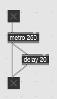
Thanks but it is doing the opposite . I need that the on time will be 20ms and the off time will be 230ms
EDIT:
ok - if I change the delay time when the metro is active it will flip the operation. How can I avoid that?

post some details about timing of motors.
Are they all independent or follow some
fixed timing ?
To be most flexible, you should address each motor
with some ID prepended, and use that ID in Arduino to address
specific motor output.
Then ... using delays might look ok, but you want to have
definite ON or OFF state.
using delays to toggle is not optimal way.
post some details about timing of motors.
Are they all independent or follow some
fixed timing ?
the timing of motor is unknown - I would like to just build the surface in max to control X amount of solenoids (just for practicing the method of sending multiple data from Max to Arduino) - so it might be that a metro will be constant every 500ms and the other every 1 sec and the other two will pulse each random interval. What I do know is that the ON time for each pulse interval should be around 20ms to 40ms and the rest of the interval should be OFF.
To be most flexible, you should address each motor
with some ID prepended,
Is it how I should do it in Max?
and use that ID in Arduino to address
specific motor output.
This is the difficult part. how can I take all the data I'm sending through Serial in Max and read that in Arduino and translate each solenoid 0 1 state to the gpio outputs?
Then ... using delays might look ok, but you want to have definite ON or OFF state. using delays to toggle is not optimal way.
What do you mean? How would you do it without delay?
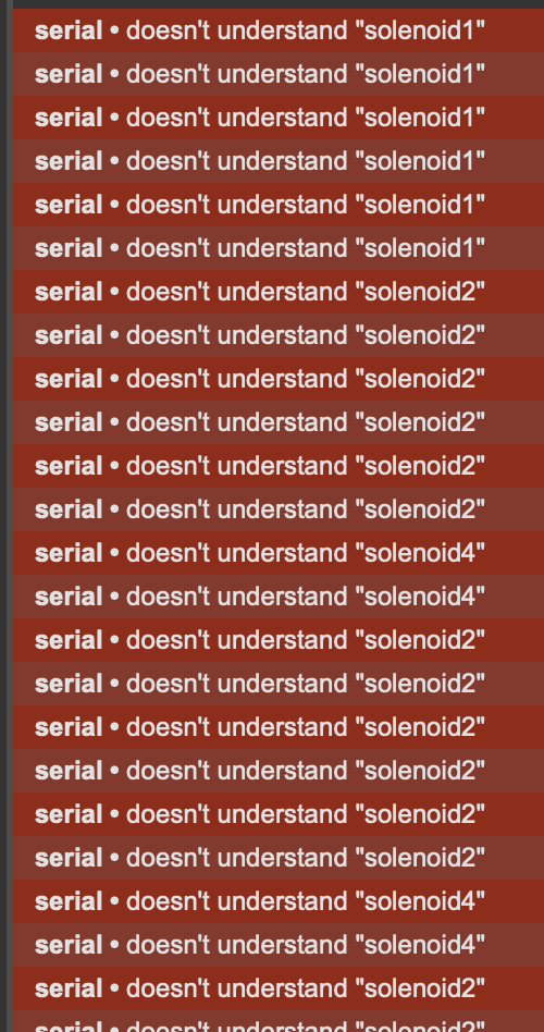
I'm getting those errors when trying to send the string from max to arduino via the serial in the above patch:

About your metro question:
About the error message you get using [serial]: of course, [serial] doesn't understand the message solenoid2. I would recommend spending some quality time with some of the Arduino Communication tutorials, for instance these ones that communicate with Max:
- https://docs.arduino.cc/built-in-examples/communication/Dimmer
- https://docs.arduino.cc/built-in-examples/communication/VirtualColorMixer
(Max code is included in the tutorials)
Thanks for your metro patch.
While the dimmer tutorial is great - they show only how to pass 1 sequence of numbers from Max to Arduino.
What happen if I want to pass few of those numbers using multiple slides in max? (to dim multiple leds for examples)
how can I separate each of those values and control different leds using arduino?
here is the max patch from the dimmer example:
Now, if that's clear, then you can do what Source Audio suggested above: send from Max to Arduino a formatted message with a different ID for each motor. For instance, you could decide that 65 is for motor 1, 66 for motor 2, etc. If you send just a 0 or a 1 to the motors, what you send from Max would look like:
65 1 (turn on motor 1)
65 0 (turn off motor 1)
67 1 (turn on motor 3)
etc.
In Arduino, you parse the code and use it accordingly. For instance:
serialvalue = Serial.read();
if (serialvalue == 65){
int motorstate = Serial.parseInt();
analogWrite(9, motorstate); // if 9 is output pin for motor 1}
else if(serialvalue == 66){
int motorstate = Serial.parseInt();
analogWrite(10, motorstate); // if 10 is output pin for motor 2}
etc.
Note: untested code, I'm just typing away here to give you an idea of the process. Basically what Source Audio was saying, I think.
Thanks - so basically we avoiding using string as an ID for each motor, rather we are using integer so it will be much easier to receive that data inside arduino.
Regarding the arduino code:
why to do if statement for each ID ? " if(serial.available == 65) " etc etc
why not just write: if (Serial.available() > 0
?
Your last question makes no sense.
Read the words carefully.
if serial available > 0 means if any data has been received.
if serial value matches 65 - is completely different thing.
I prefer using a letter for ID than using numeric ID.
is more secure in case other values than just 0 or 1 need to be sent.
In that minimal configuration - 4 on off states,
you can also use only numbers without ID of any kind.
1 = motor 1 Off, 2 = motor 1 On,
3 = motor 2 Off, 4 = motor 2 Off
and so on.
add also a value for all on or all off etc.
Your other option is to send a list of 4 values, and parse them as 4 values / outputs in Arduino.
Optimal code allwas depends on the whole, and not some snippets.
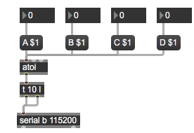
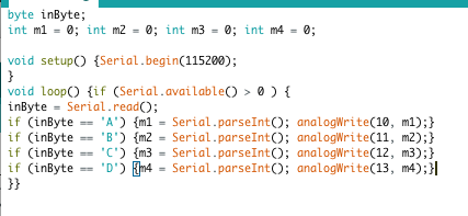
The below combination working just fine - but If I want to have an ID that is Letter for each motor/solenoid - how can I read that in the arduino?
My max patch is as following:
I'm using your arduino code I found in some other post:
int pin;
int state;
void setup ()
{
  Serial.begin(115200);

  //turns all Off
  for (int i=2; i < 14; i++)
  {
    digitalWrite(i, 0);
  }
}

void loop()
{
  if (Serial.available() > 0)
  {
    pin = Serial.parseInt();
    state = Serial.parseInt();
    if (Serial.read() == '\n')
    {
      digitalWrite(pin, state);
    }
  }
}
adjust to analogWrite to correct pins :
adjust to analogWrite to correct pins:
Thank I'll try that. If I would like to control digital pin (only On and Off states) I should use the "digitalWrite" function ?
analogWrirte would be for PWM, LED fading etc,
if you only need on off, then digitalWrite.
I posted that analog example beause you asked about it in previous mail.
Thanks! Thanks to your code I think I'm finally understand how to receive strings inside arduino and route them! Will read on Serial.ParsInt() asap
one thing I'm not quite understand:
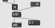
We are using to atoi object which translating ascii data type to integers right?
so the Serial is receiving integers and not strings.
Why then inside arduino we compare the input data as it was string? 'A' 'B' etc ? the inByte is an integer number isn't it?
A is a string
'A' is the ascii code for the string, i.e. an integer (65 for A, 66 for B...)
Edit:
All working just fine.
Thanks for all the help and explanations!
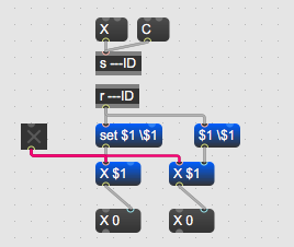
I try to build an abstraction for the pulsing events
here is my abstraction:
when connecting the output of that abstraction to the serial object it is not working.
When having that abstraction as stand alone (meaning no abstraction) it is working as it should.
Any idea why?
Did you doubleclick that abstraction as embeded patch to
see what is going on inside ?
take one or the other of this 2 examples to set message
with included $1 argument.
-----------
String is in arduino language list of elements.
Serial communication in general is 8bit protocol,
means data is transmitted as raw bytes 0 - 255.
It is a matter of parsing that data to form either
ASCII representation of collected bytes, or to simply use integers.
Like midi does.
For example if you send 49 it can be interpreted in arduino as raw byte 49
or as ASCII digit 1.
to receive number 333 you need to send 51 51 51 and 10 (linefeed)
and parse that 3 digits as integer 333.
so you either send list 51 51 51 10 to serial object directly,
or 333 to atoi and append ascii 10 as linefeed.
Parsing integers (or floats) is a bit tricky in arduino,
because if received bytes do not carry linefeed (ascii 10) to define
end of collection of digits, or nondigit ASCII byte, after a default timeout of 1000ms arduino spits out zero.
Did you doubleclick that abstraction as embeded patch to
see what is going on inside ?
I'm not sure what was it but it seems to work now (the abstraction I build)
take one or the other of this 2 examples to set message
with included $1 argument.
what is that use of the \ sign ? Never seeing that before.
using one of your two example will not work as abstraction with setting arguments from outside patch using the # sign (?)
For example if you send 49 it can be interpreted in arduino as raw byte 49
or as ASCII digit 1.
is there a default interpretation? who decide if arduino will interpreted it as raw byte 49? (meaning integer?) or as ASCII digit 1 ?
to receive number 333 you need to send 51 51 51 and 10 (linefeed)
and parse that 3 digits as integer 333.
what does parsing mean? is it releated to the object Serial.parstint() ?
the Serial.parstint() object translating ASCII code to integers?
You should start reading arduino documentation.
I have no time to answer that basic questions.
Thanks for all your help!