
Get values of jit.matrix. Control with OSC message one strip of 64 led as a matrix 8*8. RESOLVED

Hello,
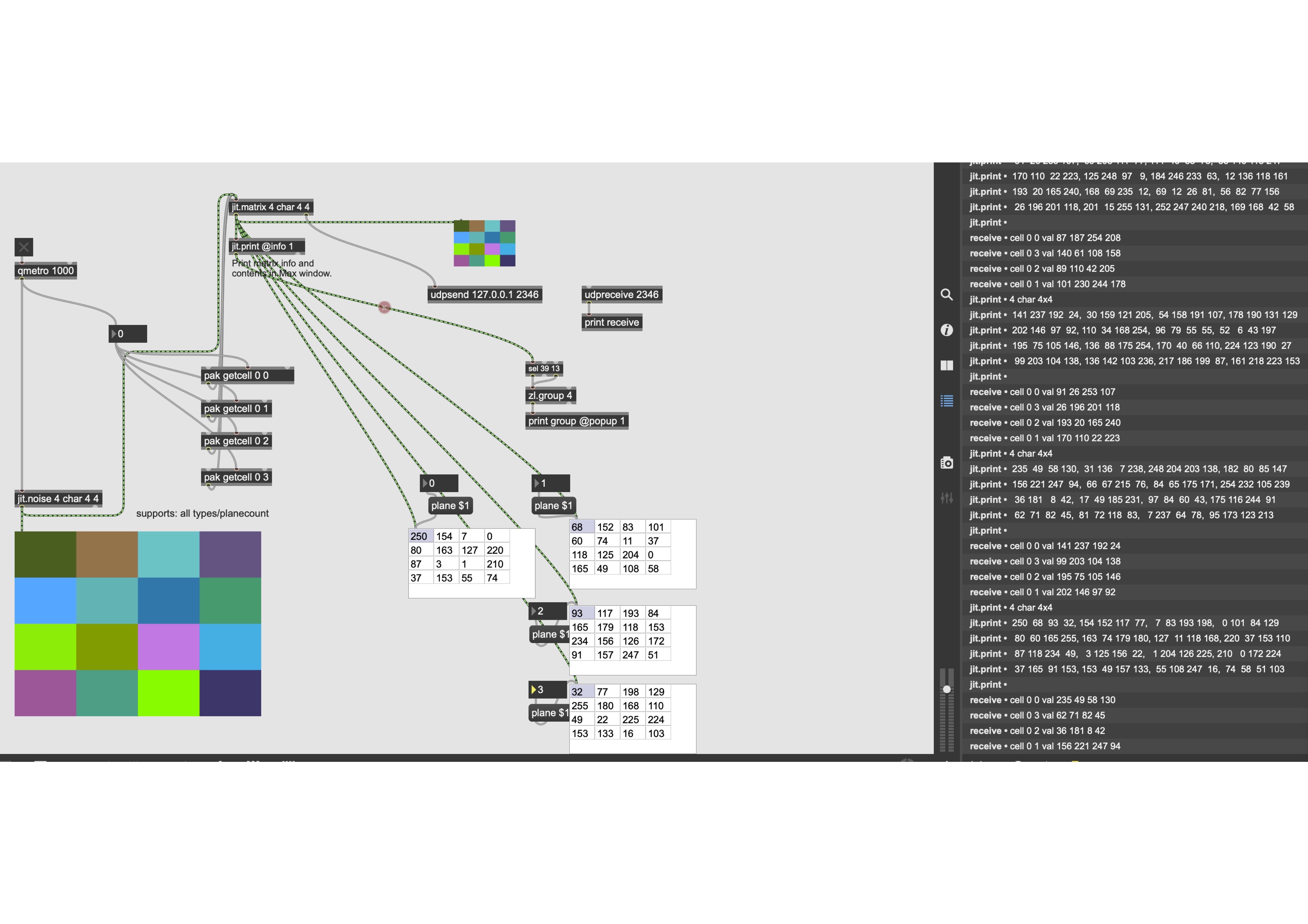
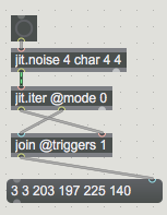
I would like values of 4*4 matrix with marker < and > in order to have those datas
< 113, 220,...,..., 110 >
In. a jit.matrix we have 4 datas/cell. That means we have 4*4 datas between < and >
I made this small patch and I think we have to use object that I can't use.
Thank you for your help
In my example I receive only the raw 0 but value are strange

receivedmess: cell 0 0 val 123 40 53 248
receivedmess: cell 0 3 val 141 132 163 180
receivedmess: cell 0 2 val 234 97 200 213
receivedmess: cell 0 1 val 226 205 19 176
receivedmess: cell 0 0 val 123 40 53 248
receivedmess: cell 0 3 val 141 132 163 180
receivedmess: cell 0 2 val 234 97 200 213
receivedmess: cell 0 1 val 226 205 19 176


The screenshot seem broken, I can't see it.
Also, for future patch sharing: select objects you want to share, then hit Edit -> "Copy compressed", then paste the code here.
What you want is unclear. Values from your pasted log doesn't look weird to me. Loking at youyr patch, your source matrix is a 4 planes char jit.noise of dim 4x4, which means that you have 4x4=16 cells, each with 4 values between 0 and 255. You're only sending getcell for the first row (row 0), which means you only gete the values of the 4 cells of that first row. This is exactly what you receives in your log.
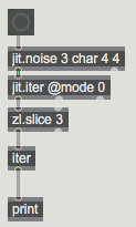
Maybe have a look at [jit.iter] or [jit.spill]. Also, if you really need to format your messages with '<' and '>', why not adding those with [pack]? Or maybe [combine] or [sprintf]?
Also, seems that you're french, I can help you in french if you struggle with english if you want.
Merci pour votre réponse.
Dois je utiliser [jit.iter] or [jit.spill] après jit.print ou jit.matrix ?
En fait, j'aimerais que les données soient bien formées dans le monitor dans receive
Pas seulement dans jit.print
I hope you understood me ?
I would like to have for cell 0 0 in receive < 234, 49, 59, 130 >
The aim is to transfer datas of each pixel to an Arduino to control a matrix of led
or may be all the 16 datas like that
< 234, ....., ..., 129 >
or
A 239
B 49
C 59
until
P 129
Apparemment vos images ne fonctionnent toujours pas :
Dois je utiliser [jit.iter] or [jit.spill] après jit.print ou jit.matrix ?
C'est pareil, l'outlet gauche de [jit.print] renvoie la matrice à l'identique.
Malheureusement, il semblerait qu'il n'y ait pas moyen d'obtenir l'output console de [jit.print] en tant que message. Mais c'est possible de recréer un message identique :
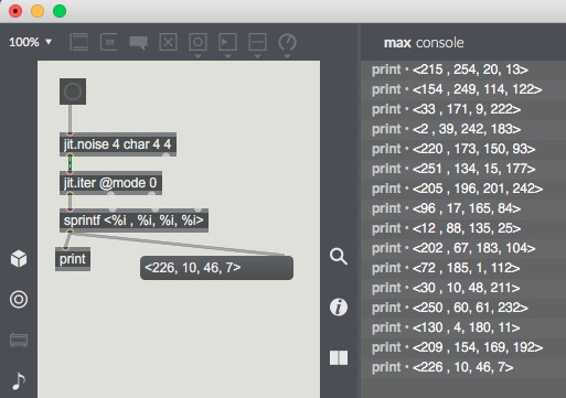
Pour rajouter les '<' et '>', il suffit de les rajouter dans le [sprintf] aux endroits voulus.
merci c'est presque bon.
Mais je n'arrive qu'à voir 32 données em meme temps, pas 64.
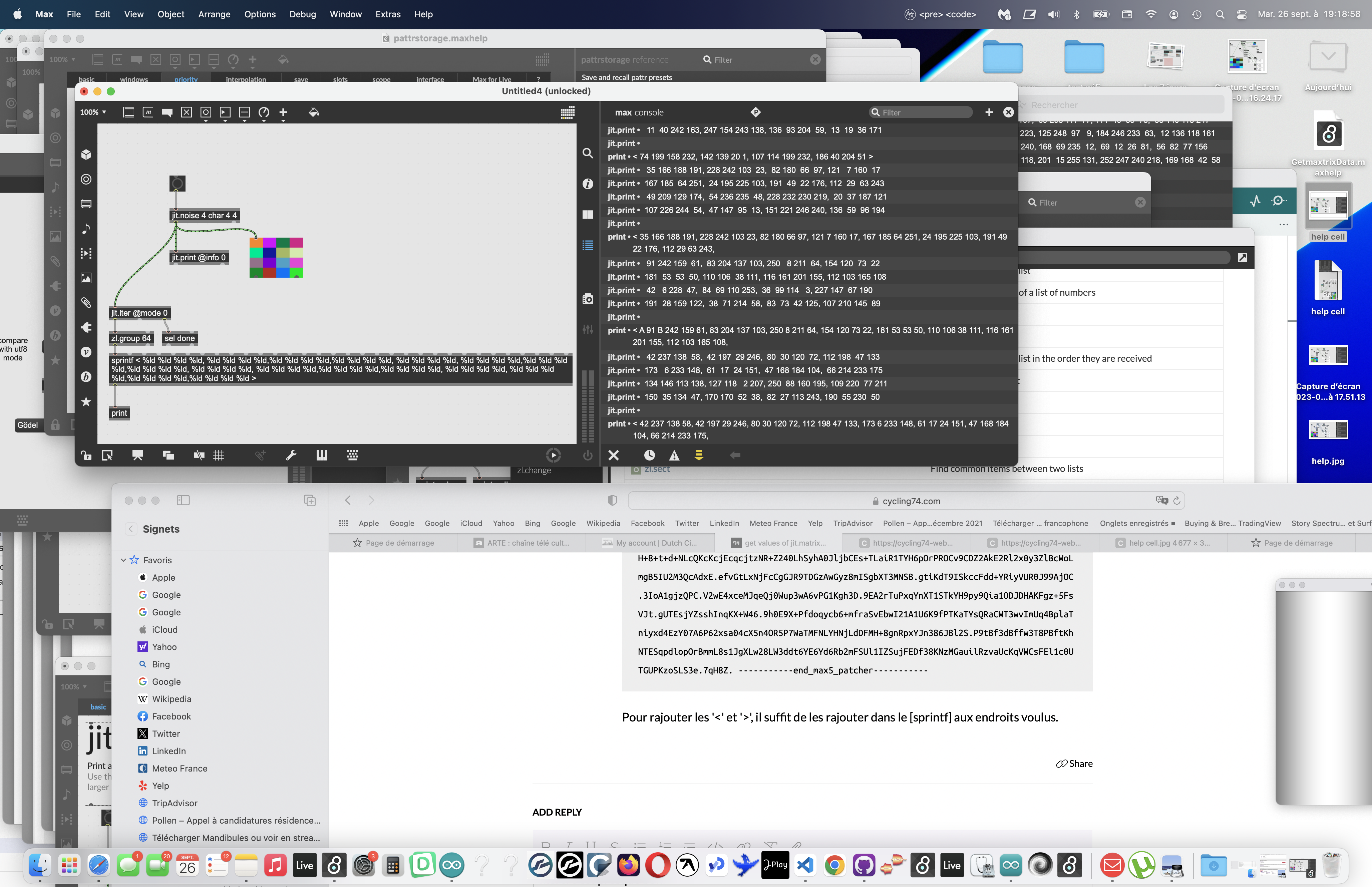
Cela semble être dû à une limitation de [sprintf], qui n'accepterait pas plus de 32 entrées. De plus, la virgule est un caractère spécial dans Max, donc je ne vois pas comment simplement outrepasser cette limitation (autrement qu'en utilisant javascript). Le plus simple serait de gérer autrement le traitement du message directement dans arduino, et par exemple d'envoyer les valeurs en une simple liste de 64 entier (sans les virgules et les '<' et '>'). Le programme arduino devra ensuite séparer les entiers 4 par 4 pour chaque pixel, puis tous les 4 pixels pour chaque ligne.
Ou alors l'update de la matrice de LED se fait tous les 4 messages (un par ligne ou colonne).

"I would like to have for cell 0 0 in receive < 234, 49, 59, 130 >"
in first place you need to know how to parse values for LED rgb matrix in Arduino.
If you don't know how to set that yourself and have to use
fixed form as above, it is simple, each cell own message:
arduino lib will tell you if you need line break or something else between cell messages.
With this fixed from, I will parse datas like that in Arduino.
I made the program below as if datas are received from the serial
I guess it is correct ?
I will see later how to adapt it to fastLed or neoPixel libraries
Thanks again ;)
//   Receive with start- and end-markers combined with parsing

const byte numChars = 200;
char receivedChars[numChars];
char tempChars[numChars];        // temporary array for use when parsing

// variables to hold the parsed data

#define numberOfDataPerLed 4
#define numberOfRow 4
#define numberOfColumn 4

int valuesOfEachLed[numberOfDataPerLed] = { 0 };

float floatFromPC = 0.0; // not used for the moment

boolean newData = false;

void setup()
{
   Serial.begin(115200);
}

void loop() {

  for(uint8_t i = 0; i < (numberOfRow*numberOfColumn); i++) // numberOfRow+numberOfColumn is the number of cell.
 {
    recvWithStartEndMarkers(); //receive 4 datas with marker 16 times?
    if (newData == true) {
        strcpy(tempChars, receivedChars);
            // this temporary copy is necessary to protect the original data
            //   because strtok() used in parseData() replaces the commas with \0
        parseData(); // 4 datas marked and separated with a coma.

        newData = false;
    }
  }
}

void recvWithStartEndMarkers() {
    static boolean recvInProgress = false;
    static byte ndx = 0;
    char startMarker = '<';
    char endMarker = '>';
    char rc;

    while (Serial.available() > 0 && newData == false) {
        rc = Serial.read();

        if (recvInProgress == true) {
            if (rc != endMarker) {
                receivedChars[ndx] = rc;
                ndx++;
                if (ndx >= numChars) {
                    ndx = numChars - 1;
                }
            }
            else {
                receivedChars[ndx] = '\0'; // terminate the string
                recvInProgress = false;
                ndx = 0;
                newData = true;
            }
        }

        else if (rc == startMarker) {
            recvInProgress = true;
        }
    }
}

void parseData() {      // split the 4 datas into its parts
    char * strtokIndx; // this is used by strtok() as an index
    strtokIndx = strtok(tempChars,",");      // get the first part - the string

    for(uint8_t i = 0; i < numberOfDataPerLed; i++)
   {
    valuesOfEachLed[i] = atoi(strtokIndx);
    strtokIndx = strtok(NULL, ",");
   }
}
you shuld start from the other end, choose library that you want to use,
read few examples to se how it works, an then adapt what you send from max.
writting arduin code without doing that first makes no sense.
it could be as simpe as sending:
0 0 255 255 255 255 line break to serial object
0 0 row - column, 4 RGB values.
no <> or commas needed.
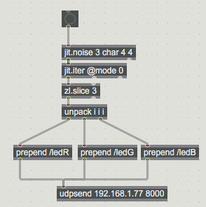
and jit.itter allready does it for you, just join
2 outlets in correct order
I agree with @Source audio!
In order to minimize the amount of data to send, I would go even further and not sending coordinates, given that you always work with a 4x4 matrix and already know the order in which cell values are sent. If you go this way, I would still send a special message once a full frame has been sent, just to make sure everything stays in sync. For that, he righmost outlet if [jit.iter] purposefully sends a "done" once it processed the full matrix!
Also, to my knowledge, RGB LED only work with RGB values, so no need for an alpha channel.
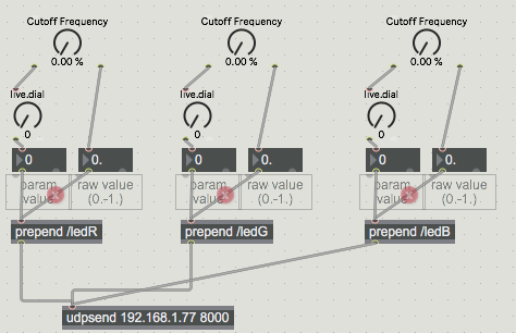
Hello.
I can't manage to get pixel one by one from max/msp.
And I don't really know how I will parse data in Arduino.
I put my programs
Arduino receive 3 Osc message ledR ledG ledB. But as the same time
I made a void parse() at the end of the program
/*---------------------------------------------------------------------------------------------

  Open Sound Control (OSC) library for the ESP8266/ESP32

  Example for receiving open sound control (OSC) messages on the ESP8266/ESP32
  Send integers '0' or '1' to the address "/led" to turn on/off the built-in LED of the esp8266.

  This example code is in the public domain.

--------------------------------------------------------------------------------------------- */
#ifdef ESP8266
#include <ESP8266WiFi.h>
#else
#include <WiFi.h>
#endif
#include <WiFiUdp.h>
#include <OSCMessage.h>
#include <OSCBundle.h>
#include <OSCData.h>

//char ssid[] = "Iphone de ben"; // your network SSID (name)
//char pass[] = "cacaprout";  // your network password

char ssid[] = "Bbox-E69F0626";       // your network SSID (name)
char pass[] = "NKg5Ad1m3mXFgx142p";  // your network password

// A UDP instance to let us send and receive packets over UDP
WiFiUDP Udp;
//const IPAddress outIp(10,40,10,105);        // remote IP (not needed for receive)
const IPAddress outIp(192, 168, 1, 77);
const unsigned int outPort = 9999;    // remote port (not needed for receive)
const unsigned int localPort = 8000;  // local port to listen for UDP packets (here's where we send the packets)

OSCErrorCode error;
unsigned int ledState = LOW;  // LOW means led is *on*

//------------ END  ESP and OSC setting

#ifndef BUILTIN_LED
#ifdef LED_BUILTIN
#define BUILTIN_LED LED_BUILTIN
#else
#define BUILTIN_LED 13
#endif
#endif

#include <FastLED.h>
#define NUM_LEDS 64 // my matrix of led is 64 pixels
#define PIN_CONTROLLING_STRIP 1
CRGB leds[NUM_LEDS];

//----------- END FastLed setting

//-----------    Receive with start- and end-markers combined with parsing

    const byte numChars = 200;
    char receivedChars[numChars];
    char tempChars[numChars];        // temporary array for use when parsing

//-----------  variables to hold the parsed data
    char messageFromPC[numChars] = {0}; //or 5 doesn't change anything

// ABOVE not USED

#define numberOfDataPerLed 3
#define numberOfLed 64

int valuesOfEachLed[numberOfDataPerLed] = { 0 };
int valueOfRed[NUM_LEDS];

int receiveRed;
int receiveGreen;
int receiveBlue;

float floatFromPC = 0.0; // not used for the moment

void setup() {
  pinMode(BUILTIN_LED, OUTPUT);
  digitalWrite(BUILTIN_LED, ledState);  // turn *on* led

  Serial.begin(115200);

  // Connect to WiFi network
  Serial.println();
  Serial.print("Connecting to ");
  Serial.println(ssid);
  WiFi.begin(ssid, pass);

  while (WiFi.status() != WL_CONNECTED) {
    delay(500);
    Serial.print(".");
  }
  Serial.println("");

  Serial.println("WiFi connected");
  Serial.println("IP address: ");
  Serial.println(WiFi.localIP());

  Serial.println("Starting UDP");
  Udp.begin(localPort);
  Serial.print("Local port: ");
#ifdef ESP32
  Serial.print("LocalportESP32: ");
  Serial.println(localPort);
#else
  Serial.println(Udp.localPort());
#endif

  // control LED with FastLed
  FastLED.addLeds<NEOPIXEL, PIN_CONTROLLING_STRIP>(leds, NUM_LEDS);
  FastLED.setBrightness(5);
  for (int i = 0; i <= NUM_LEDS; i++) {
    leds[i] = CRGB(0, 0, 0);  // turn off all
    FastLED.show();
  }
}

void loop() {
  OSCMessage msg;
  int size = Udp.parsePacket();

  if (size > 0) {
    while (size--) {
      msg.fill(Udp.read());
    }
    if (!msg.hasError()) {
      msg.dispatch("/ledR", ledR); // tracking Red
      msg.dispatch("/ledG", ledG); // tracking Green
      msg.dispatch("/ledB", ledB); // tracking Blue
    } else {
      error = msg.getError();
      Serial.print("error: ");
      Serial.println(error);
    }
  }

  for (int i = 0; i < NUM_LEDS; i++) {
 leds[i] = CRGB ( valueOfRed[i],receiveGreen,receiveBlue);
  }
  FastLED.show();
}

void ledR(OSCMessage &msg) {
  receiveRed = msg.getInt(0);
    Serial.print("/ledR:receiveRed ");
    Serial.println(receiveRed);

    for (int i = NUM_LEDS-2; i <= NUM_LEDS; i++) { // only two last pixel are mixed with red
    valueOfRed[i]= receiveRed;  // only first become red
    }
    FastLED.show();
}

void ledG(OSCMessage &msg) {
  receiveGreen = msg.getInt(0);
    Serial.print("/ledG: ");
    Serial.println(receiveGreen);
    FastLED.show();
}
void ledB(OSCMessage &msg) {
  receiveBlue = msg.getInt(0);
    Serial.print("/ledB: ");
    Serial.println(receiveBlue);
    FastLED.show();
}


void parseData() {      // split the 31 data into its parts
    char * strtokIndx; // this is used by strtok() as an index
    strtokIndx = strtok(tempChars,",");      // get the first part - the string

    for(uint8_t i = 0; i < numberOfDataPerLed; i++)
   {
    valuesOfEachLed[i] = atoi(strtokIndx);
    strtokIndx = strtok(NULL, ",");
    Serial.print (i);
    Serial.print (" ");
    Serial.print (valuesOfEachLed[i]);
    Serial.print (",");
   }
    Serial.println ("");
}Dude, be carreful, you're exposing your wifi an tether passwords to the world...
It is not clear where you have a problem. The Arduino receives the OSC messages but then nothing happen, is that it?
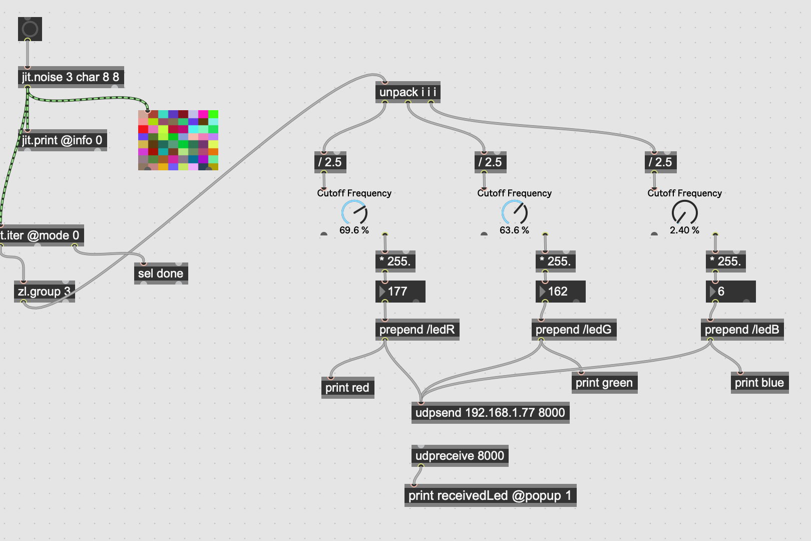
Also, your Max patch doesn't make sens: I assume you want a value between 0 and 255 for each color, not between 0 and 100 like it is now, right? Also, I don't get the relationship between your 4x4 noise matrix and your 3 knobs. Are the knobs only for some debug/vizualiation purpose? If I get what you're looking for, here is a fixed version of your patch even if that doesn't make too much sense:
As for the arduino program: you don't even use your parseData() function so it is simply useless. I'm not familiar with OSC libraries in Arduino so I don't really know how they behave.
You should really start simple, try first by sending only one color (on list of 3 values), and dispay that same color on all of your leds. Once this is working, add the necessary bits to allow updating each led individually.
Honestly, I expected this.
what shud this be good for ????
you send int and foat at same time to ESP8266 ?
but here is answer to your question :
if you want all pixels ( which are 16 x 3)
itered, as you say all pixels one by one,
make this :
if you wan to send 16 lists split to 3 values, try this :
-------
Thanks.
It is almost good.
Here the matrix as I have actually
But when I bang on Max/Msp, my 10 first leds change, then with the next bang, only 8 next leds change. I would like a change of 64 datas at once.
18:54:47.901 -> Local port: LocalportESP32: 8000
18:54:51.726 ->  valueOfRed 1  84
18:54:51.726 ->  valueOfRed 2  230
18:54:51.726 ->  valueOfRed 3  217
18:54:51.726 ->  valueOfRed 4  198
18:54:51.758 ->  valueOfRed 5  107
18:54:51.758 ->  valueOfRed 6  218
18:54:51.791 ->  valueOfRed 7  34
18:54:51.791 ->  valueOfRed 8  107
18:54:51.824 ->  valueOfRed 9  115
18:54:51.825 ->  valueOfRed 10  25
18:54:53.970 ->  valueOfRed 11  225
18:54:53.970 ->  valueOfRed 12  127
18:54:54.001 ->  valueOfRed 13  126
18:54:54.001 ->  valueOfRed 14  25
18:54:54.001 ->  valueOfRed 15  12
18:54:54.035 ->  valueOfRed 16  187
18:54:54.035 ->  valueOfRed 17  216
18:54:54.035 ->  valueOfRed 18  76
18:55:21.744 ->  valueOfRed 19  5
18:55:21.744 ->  valueOfRed 20  47
18:55:21.744 ->  valueOfRed 21  172
18:55:21.744 ->  valueOfRed 22  226
18:55:21.777 ->  valueOfRed 23  66
Here Arduino sketch. ( just the end has been changed)
/*---------------------------------------------------------------------------------------------

  Open Sound Control (OSC) library for the ESP8266/ESP32

  Example for receiving open sound control (OSC) messages on the ESP8266/ESP32
  Send integers '0' or '1' to the address "/led" to turn on/off the built-in LED of the esp8266.

  This example code is in the public domain.

--------------------------------------------------------------------------------------------- */
#ifdef ESP8266
#include <ESP8266WiFi.h>
#else
#include <WiFi.h>
#endif
#include <WiFiUdp.h>
#include <OSCMessage.h>
#include <OSCBundle.h>
#include <OSCData.h>

//char ssid[] = "Iphone de ben"; // your network SSID (name)
//char pass[] = "cacaprout";  // your network password

char ssid[] = "Bbox-E69F0626";       // your network SSID (name)
char pass[] = "NKg5Ad1m3mXFgx142p";  // your network password

// A UDP instance to let us send and receive packets over UDP
WiFiUDP Udp;
//const IPAddress outIp(10,40,10,105);        // remote IP (not needed for receive)
const IPAddress outIp(192, 168, 1, 77);
const unsigned int outPort = 9999;    // remote port (not needed for receive)
const unsigned int localPort = 8000;  // local port to listen for UDP packets (here's where we send the packets)

OSCErrorCode error;
unsigned int ledState = LOW;  // LOW means led is *on*

//------------ END  ESP and OSC setting

#ifndef BUILTIN_LED
#ifdef LED_BUILTIN
#define BUILTIN_LED LED_BUILTIN
#else
#define BUILTIN_LED 13
#endif
#endif

#include <FastLED.h>
#define NUM_LEDS 64
#define PIN_CONTROLLING_STRIP 1
CRGB leds[NUM_LEDS];

//----------- END FastLed setting

//-----------    Receive with start- and end-markers combined with parsing

    const byte numChars = 200;
    char receivedChars[numChars];
    char tempChars[numChars];        // temporary array for use when parsing

//-----------  variables to hold the parsed data
    char messageFromPC[numChars] = {0}; //or 5 doesn't change anything

// ABOVE not USED

#define numberOfDataPerLed 3
#define numberOfLed 64

int valuesOfEachLed[numberOfDataPerLed] = { 0 };

int valueOfRed[NUM_LEDS];
int valueOfGreen[NUM_LEDS];
int valueOfBlue[NUM_LEDS];
int j; // positionOfLedOnTheStrip
int k; // positionOfLedOnTheStrip
int l; // positionOfLedOnTheStrip

int receiveRed;
int receiveGreen ;
int receiveBlue;

float floatFromPC = 0.0; // not used for the moment

boolean newData = false;

void setup() {
  pinMode(BUILTIN_LED, OUTPUT);
  digitalWrite(BUILTIN_LED, ledState);  // turn *on* led

  Serial.begin(115200);

  // Connect to WiFi network
  Serial.println();
  Serial.println();
  Serial.print("Connecting to ");
  Serial.println(ssid);
  WiFi.begin(ssid, pass);

  while (WiFi.status() != WL_CONNECTED) {
    delay(500);
    Serial.print(".");
  }
  Serial.println("");

  Serial.println("WiFi connected");
  Serial.println("IP address: ");
  Serial.println(WiFi.localIP());

  Serial.println("Starting UDP");
  Udp.begin(localPort);
  Serial.print("Local port: ");
#ifdef ESP32
  Serial.print("LocalportESP32: ");
  Serial.println(localPort);
#else
  Serial.println(Udp.localPort());
#endif

  // control LED with FastLed
  FastLED.addLeds<NEOPIXEL, PIN_CONTROLLING_STRIP>(leds, NUM_LEDS);
  FastLED.setBrightness(250);
  for (int i = 0; i <= NUM_LEDS; i++) {
    //  leds[i] = CRGB ( 2*i,255-(2*i), 255-(2*i));
    leds[i] = CRGB(0, 0, 0);  // turn off all
    FastLED.show();
  }
}

void loop() {
  OSCMessage msg;
  int size = Udp.parsePacket();

  if (size > 0) {
    while (size--) {
      msg.fill(Udp.read());
    }
    if (!msg.hasError()) {
      msg.dispatch("/ledR", ledR);
      msg.dispatch("/ledG", ledG);
      msg.dispatch("/ledB", ledB);
    } else {
      error = msg.getError();
      Serial.print("error: ");
      Serial.println(error);
    }
  }

  for (int i = 0; i < NUM_LEDS; i++) {
  // leds[i] = CRGB ( valueOfRed[j],valueOfGreen[k],valueOfBlue[l]);
   leds[i] = CRGB ( valueOfRed[i],valueOfGreen[i],valueOfBlue[i]);
  }
  FastLED.show();
}

void ledR(OSCMessage &msg) {

    receiveRed = msg.getInt(0);

    j++;
    j=j%NUM_LEDS;

    valueOfRed[j]= receiveRed;  // only first become red
    Serial.print(" valueOfRed "); Serial.print(j);Serial.print("  ");
    Serial.println(valueOfRed[j]);

}

void ledG(OSCMessage &msg) {
  receiveGreen = msg.getInt(0);

    k++;
    k=k%NUM_LEDS;

    valueOfGreen[k]= receiveGreen;  // only first become red
   // Serial.print(" valueOfGreen "); Serial.print(k);Serial.print("  ");
   // Serial.println(valueOfGreen[k]);

}

void ledB(OSCMessage &msg) {
  receiveBlue = msg.getInt(0);

    l++;
    l=l%NUM_LEDS;

    valueOfBlue[l]= receiveBlue;  // only first become red
  //  Serial.print(" valueOfBlue "); Serial.print(l);Serial.print("  ");
  //  Serial.println(valueOfBlue[l]);

}Image still not displaying. Maybe it's due to uncommon characters in the file name. Try something simple like "screenshot.PNG" instead of the default macOS default "Capture d'écran 2023-09-27 à 18.50.35.png".
matrix with 3 layer (r, g, b). 8 row 8 column
But when I bang on Max/Msp, my 10 first leds change, then with the next bang, only 8 next leds change. I would like a change of 64 datas at once.
It could be a timing issue: maybe Max sends OSC data too fast for the Arduino to process them. You could debug this by sending a known matrix (for example with cell 0 0 val 0 0 0, cell 0 1 val 0 1 0....... cell 4 7 val 4 7 0 and so on), so you could know if some cells are skiped or not.
If that's the case, you have two solutions: either change your arduino program in a way that it makes sure to fetch all the data before displaying them, something like this:
void loop() {
  while (number_of_received_packets < NUM_LEDS * 3) {
    OSCMessage msg;
    size = Udp.parsePacket();

    if (size > 0) {
    while (size--) {
      msg.fill(Udp.read());
    }
    if (!msg.hasError()) {
      msg.dispatch("/ledR", ledR);
      msg.dispatch("/ledG", ledG);
      msg.dispatch("/ledB", ledB);
      number_of_received_packets += 1;
    } else {
      error = msg.getError();
      Serial.print("error: ");
      Serial.println(error);
    }
  }

  for (int i = 0; i < NUM_LEDS; i++) {
  // leds[i] = CRGB ( valueOfRed[j],valueOfGreen[k],valueOfBlue[l]);
   leds[i] = CRGB ( valueOfRed[i],valueOfGreen[i],valueOfBlue[i]);
  }
  FastLED.show();
}
But that could still lead to timing issues.
My best bet would stilll be to send the whole matrix as one big message and parse it into the Arduino.
Thank for your reply
I changed loop() in Arduino but I have this message errorCompilation error: 'size' was not declared in this scope
So I add int size;
But still the same problem.
So, do you think it is possible to send 64*3 datas separated with a coma","
I ask because I think we ever tried ?!
and in Arduino add we can parse()
something like that
void parseData() {      // split the 64* 3 data into its parts
    char * strtokIndx; // this is used by strtok() as an index
    strtokIndx = strtok(tempChars,",");      // get the first part - the string

    for(uint8_t i = 0; i < numberOfDataPerLed; i++)
   {
    valuesOfEachLed[i] = atoi(strtokIndx);
    strtokIndx = strtok(NULL, ",");
    Serial.print (i);
    Serial.print (" ");
    Serial.print (valuesOfEachLed[i]);
    Serial.print (",");
   }
    Serial.println ("");
}
valuesOfEachLed[i] should be
valuesOfEachLed[0] = the red of cell 0 0
valuesOfEachLed[1] = the green of cell 0 0
valuesOfEachLed[63] = the blue of cell 8 8
I'm note sure at all to be able to do that :/
My code was pseudo code, i can't even test it as I don't have the required hardware. It was just here for the logic.
According to the OSC library documentation, you can get any int from a list by using msg.getInt(i) where i is the index of the int you want.
So if you send the message "/matrixdata 100 50 0 20 30 60" (example with two leds) you could parse it this way:
void loop {
  ....
  msg.dispatch("/matrixdata", parseData);
  ...
}

void parseData(OSCMessage &msg) {
  for (uint8_t i = 0; i < NUM_LEDS; i++) {
    leds[i] = CRGB (msg.getInt(i*3), msg.getInt(i*3+1), msg.getInt(i*3+2));
  }
  FastLED.show();
}
I hope you get the logic.
Alos, I never used FastLED so I might be mistaken about how to use it.
you are fighting here on several fronts.
as first, do you know if you did set your ESP board for fast communication ?
doesn't look so.
as second :
how should it work to parse 3 RGB values 64 times
and at same time run for (int i = 0; i < NUM_LEDS; i++) loop iteration with number of leds ?
You think it will wait with iteration for each parsed 3 RGB values to continue ?
this is unefficient, you should prepend LED ID and send messge as 4 items,LED number + 3 values, then parse as one list per LED
just in case you choose to parse full list:
if leds count is 0, i = 0, i+1 = 1, i+2 = 2
if leds count is 1, i = 1, i+1 = 2, i+2 = 3 / should be 3 4 5 , or ?
leds[i] = CRGB (msg.getInt(i*3), msg.getInt(i*3+1), msg.getInt(i*3+2));
Thanks Source audio for pointing that mistake out! I guess I was too sleepy while writing this. I just edited the post.
Hello.
I parse datas as you said
At first bang I have this in ArduinoOnly seven first led are well assigned.
led number 10 is actually data from led number 38.
 led number 1 r64 g107 b246
 led number 2 r243 g247 b134
 led number 3 r55 g234 b165
 led number 4 r13 g151 b4
 led number 5 r173 g158 b229
 led number 6 r10 g191 b83
 led number 7 r151 g209 b161
 led number 8 r32 g38 b14
 led number 9 r44 g24 b154
 led number 10 r17 g194 b37
Here the 64 led from Max
matrixData: 64 107 246
matrixData: 243 247 134
matrixData: 55 234 165
matrixData: 13 151 4
matrixData: 173 158 229
matrixData: 10 191 83
matrixData: 151 209 161
matrixData: 178 47 76
matrixData: 113 155 232
matrixData: 230 213 129
matrixData: 59 97 150
matrixData: 245 175 209
matrixData: 32 38 14
matrixData: 235 223 214
matrixData: 245 162 182
matrixData: 56 105 167
matrixData: 130 172 152
matrixData: 199 60 143
matrixData: 183 70 168
matrixData: 93 251 222
matrixData: 56 250 67
matrixData: 182 1 9
matrixData: 137 234 190
matrixData: 31 138 212
matrixData: 150 94 227
matrixData: 118 21 167
matrixData: 44 24 154
matrixData: 3 113 230
matrixData: 84 121 212
matrixData: 251 19 156
matrixData: 240 13 7
matrixData: 123 62 128
matrixData: 168 102 83
matrixData: 82 192 115
matrixData: 129 23 50
matrixData: 123 86 133
matrixData: 131 202 173
matrixData: 21 149 203
matrixData: 163 217 185
matrixData: 17 194 37
matrixData: 79 212 4
matrixData: 90 139 183
matrixData: 254 151 28
matrixData: 5 35 53
matrixData: 165 33 99
matrixData: 106 122 35
matrixData: 87 107 91
matrixData: 254 18 46
matrixData: 138 62 163
matrixData: 212 193 170
matrixData: 18 126 122
matrixData: 59 127 53
matrixData: 6 2 77
matrixData: 166 148 227
matrixData: 64 240 136
matrixData: 224 238 133
matrixData: 207 112 111
matrixData: 80 216 157
matrixData: 45 240 72
matrixData: 177 70 22
matrixData: 49 102 38
matrixData: 202 168 46
matrixData: 4 11 235
matrixData: 6 174 200At second bang I have ten other leds turn on but without good assignment.
I send r g b, 64 times but in Arduino I receive only 10 datas not very well assigned.
Here 's how I parse datas in Arduino
void loop() {
 // while (number_of_received_packets < NUM_LEDS * 3) {
    OSCMessage msg;
    size = Udp.parsePacket();

    if (size > 0) {
    while (size--) {
      msg.fill(Udp.read());
    }

    if (!msg.hasError()) {

     // msg.dispatch("/matrixdata", parseData);
      msg.dispatch("/matrixdata",assignDataParsed); // read only 3*10 datas ? not 3*64. same problem with below ?

     /*. only ten datas as the same time
      msg.dispatch("/ledR", ledR);
      msg.dispatch("/ledG", ledG);
      msg.dispatch("/ledB", ledB);
     */
      number_of_received_packets += 1;
    }

    else {
      error = msg.getError();
      Serial.print("error: ");
      Serial.println(error);
    }
  }

  for (int i = 0; i < NUM_LEDS; i++) { //
  // leds[i] = CRGB ( valueOfRed[j],valueOfGreen[k],valueOfBlue[l]);
  // leds[i] = CRGB ( valueOfRed[i],valueOfGreen[i],valueOfBlue[i]);
  }
//  FastLED.show();
 // }
}

void assignDataParsed(OSCMessage &msg) {

  for (uint8_t i = 0; i < 1; i++) {
   j=j+1;
   j%=NUM_LEDS;

    leds[j] = CRGB (msg.getInt(i*3), msg.getInt(i*3+1), msg.getInt(i*3+2)); //
    Serial.print (" led number "); Serial.print (j);  Serial.print ("");
    Serial.print ( " r"); Serial.print (msg.getInt(i*3));
    Serial.print ( " g"); Serial.print (msg.getInt(i*3+1));
    Serial.print ( " b"); Serial.println (msg.getInt(i*3+2));

  }
  FastLED.show();
}You need to be more precise.
I parse datas as you said
Which parsing method are you refering to? The one in this post or the one in that post?
For the first one, I can't help without looking at your whole max patch and arduino code. For the second one, make sure to send all the matrix data in one message like so:
Thank u.
It works !
but the color of my leds don't really match with those of max.
I think I have to set HSV color too.
Thank u to all! ;)
i parse data like that
void assignDataParsed(OSCMessage &msg) {

  for (uint8_t i = 0; i < NUM_LEDS; i++) {

    Serial.print (" led number "); Serial.print (i);  Serial.print ("");
    Serial.print ( " r"); Serial.print (msg.getInt(i*3));
    Serial.print ( " g"); Serial.print (msg.getInt(i*3+1));
    Serial.print ( " b"); Serial.println (msg.getInt(i*3+2));

    leds[i] = CHSV (msg.getInt(i*3), msg.getInt(i*3+1), msg.getInt(i*3+2)); //

  }
  FastLED.show();
}
Learning by doing, but this becomes somewhat exhausting discussion.
TFL is trying hard to help you , but infos you provide are really sparse.
Lay down what is exact control you need for your matrix led unit
using library of your choice first.
then - get rid of that printing stuff, if you use wifi
you can not print anywhere, it is only waste of chars to read when one wants to help you, and it can also disturb timing of your functions.
do you need to use CRGB insted of CHSV ?
do you know what that means and why did you use CHSV in your code ?
you send RGB values, or ?
you should read this first and if needed translate to your language to understand it:
https://github.com/FastLED/FastLED/wiki/Pixel-reference
I'm sorry.
I will ask my question in wright way next time.
My last problem now is not CRGB or CHSV, but the way to control color to my matrix of led.
My matrix of 8*8 led is actually one strip of 64 led.
So I have to transfrom matrix from Max/Msp into one strip of 64 led.
Datas from matrix in Max are send in the way ABCDEFGHI
00 10 20. ABC. 123
01 11 21. DEF. 456
02 12 22. GHI. 789
But my led of strip receive datas like that
ADGBEHCFI. -> 1 4 7 2 5 8 3 6 9
How to transform received position in Arduino?
How to transform 1 2 3 4 5 6 7 8 9 to 1 4 7 2 5 8 3 6 9 ?
Is it possible?
may be I say in Arduino
if I==1 --> J==1;
If I==2 --> J==4;
and so on?
why in Arduino ?
in max it is easier to grup all R, all G and all B values in that order,
or in any order you want.
you should have posted your LED strip model in first place,
instead of talking about 8 x 8 matrix
Yes, I should have.
Next time I will explain the whole project.
What is the object that allows you to change the order of sending data?
Actually I need to transform this data
1 2 3 4 5 6 7 8
9 10 11 12 13 14 15 16
17 18 19. .. ............................
. ... ... ... ... ... ... ... ... ... ... ... ... ... ..
. ... ... ... ... ... ... ... ... ... ... ... ... ... ..
. ... ... ... ... ... ... ... ... ... ... ... ... ... ..
. ... ... ... ... ... ... ... ... ... ... ... ... ... ..
. ... ... ... ... ... ... ... ... ... ... ... ... .64
to this data (following the shape of my 64 leds strip)
1 2 3 4 5 6 7 8
16 15 14 13 12 11 10 9
17 18 19 20 21 22 23 24
32 31 ....................................25
33 34.......................................40
48 ________________________ 41
49________________________ 56
64_______________________ _57
I must say you are hard worker !
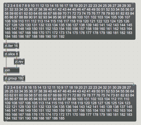
you need 8 numbers straight,then next 8 reversed,
again 8 straight, 8 reversed,
and so on till the end.
Thanks for your help so on and on ;)
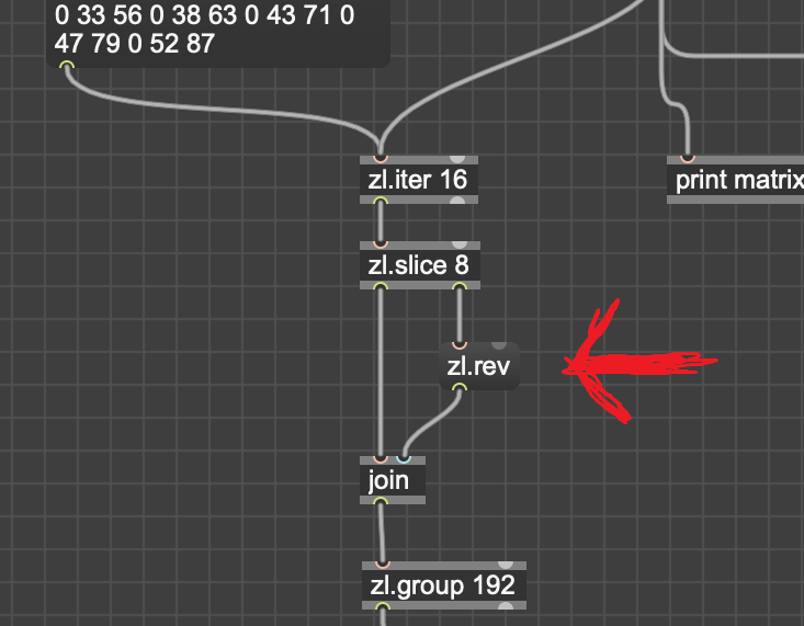
I did as your screen shot. But I have datas strange. not only number after the second zl.group 192
First you say you need to send a 4x4 matrix in a <r1, g1, b1, r2, g2, b2, ...> format, then you make us realize that the comma and <> are not necessary, then it's a 8x8 matrix, then its not a 8x8 matrix but a 1x64 one and you tell us that the data must be ordered as in "r1 r2 r3 r4..... g1 G2 g3 g4... b1 b2 b3 b4", then it must be in another, reay uncommon, order...
Benjamin, at this point, please tell us the model or reference of the led strip you use, so we can check its documentation by ourselves and know which is the most efficient way to send data to that led strip. AND that could be helpfull for future people.
Also, if in Max you work with RGB colors, just keep RGB and use the CRGB function in arduino, no need to switch to HSV. FastLED sends RGB anyway, so if you work with the CHSV function in arduino, it will require extra processing on CPU.
This is supposed to be an object, not a message. Once fixed, you will need to either close and open your patch, or send the "zlclear" message to all [zl.group] to reset them.
ok, maybe I miunerstood it a bit.
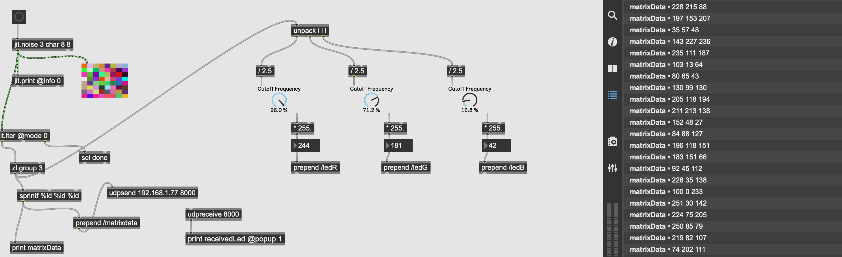
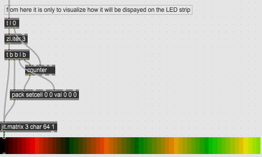
see this exampe - it referes to192 color values
which should be the input
table is in umenu object
The thing is I gave little examples of what I needed in order to be understandable.
Ideally I want to control a matrix of 8*8 of RGB leds.
Actually, i have a pseudo matrix of led. It is a single strip of 64 led in "zigzag".
I'm sorry but I saw that arrangement of led only when I experimented with.
When we will manage to do that I will be helpful for many people I think ;)
Okay, that makes much more sense now!
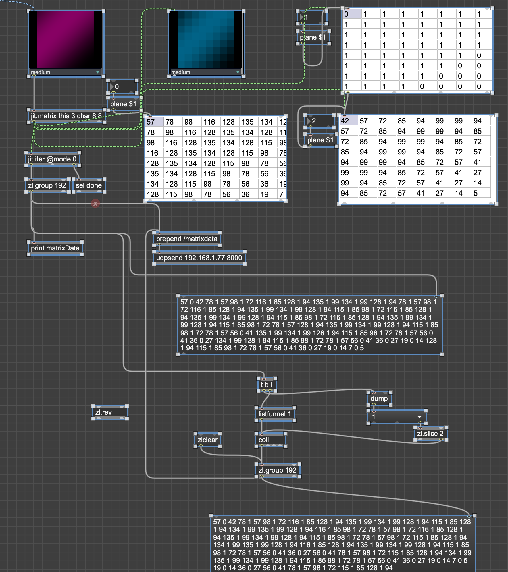
Actually you don't want to simply reverse one line every two line, you also want to keep rgb data in the correct r, then g, then b order. I think I managed to do it:
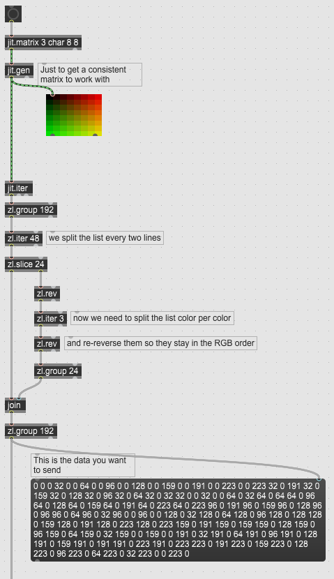
No need for any change on the Arduino side.
EDIT: updated the included patcher to replace [zl.group 192]-> [zl.iter 48] by [zl.group 48]
Hallelujah Everything works perfectly. Data sent by wifi without latency!
Here the program to receive data with wifi (OSC message) and control the strip led of 64 led RGB arranged as a 8*8 matrix (in zigzag arrangement)
/*---------------------------------------------------------------------------------------------

  Open Sound Control (OSC) library for the ESP8266/ESP32

  Example for receiving open sound control (OSC) messages on the ESP8266/ESP32
  Send integers '0' or '1' to the address "/led" to turn on/off the built-in LED of the esp8266.

  This example code is in the public domain.

--------------------------------------------------------------------------------------------- */
#ifdef ESP8266
#include <ESP8266WiFi.h>
#else
#include <WiFi.h>
#endif
#include <WiFiUdp.h>
#include <OSCMessage.h>
#include <OSCBundle.h>
#include <OSCData.h>

//char ssid[] = "name"; // your network SSID (name)
//char pass[] = "password";  // your network password

// A UDP instance to let us send and receive packets over UDP
WiFiUDP Udp;
//const IPAddress outIp(10,40,10,105);        // remote IP (not needed for receive)
const IPAddress outIp(192, 168, 1, 77);
const unsigned int outPort = 9999;    // remote port (not needed for receive)
const unsigned int localPort = 8000;  // local port to listen for UDP packets (here's where we send the packets)

OSCErrorCode error;
unsigned int ledState = LOW;  // LOW means led is *on*

//------------ END  ESP and OSC setting

#ifndef BUILTIN_LED
#ifdef LED_BUILTIN
#define BUILTIN_LED LED_BUILTIN
#else
#define BUILTIN_LED 13
#endif
#endif

#include <FastLED.h>
#define NUM_LEDS 64
#define PIN_CONTROLLING_STRIP 1
CRGB leds[NUM_LEDS];

//----------- END FastLed setting

//-----------    Receive with start- and end-markers combined with parsing

    const byte numChars = 200;
    char receivedChars[numChars];
    char tempChars[numChars];        // temporary array for use when parsing

//-----------  variables to hold the parsed data
    char messageFromPC[numChars] = {0}; //or 5 doesn't change anything

// ABOVE not USED

#define numberOfDataPerLed 3
#define numberOfLed 64

int number_of_received_packets;// = 0;
int size;

//String ledR, ledB, ledG;

int valuesOfEachLed[numberOfDataPerLed] = { 0 };

int valueOfRed[NUM_LEDS];
int valueOfGreen[NUM_LEDS];
int valueOfBlue[NUM_LEDS];
int j; // positionOfLedOnTheStrip
int k; // positionOfLedOnTheStrip
int l; // positionOfLedOnTheStrip

int receiveRed;
int receiveGreen ;
int receiveBlue;

float floatFromPC = 0.0; // not used for the moment

boolean newData = false;

void setup() {
  pinMode(BUILTIN_LED, OUTPUT);
  digitalWrite(BUILTIN_LED, ledState);  // turn *on* led

  Serial.begin(115200);

  // Connect to WiFi network
  Serial.println();
  Serial.println();
  Serial.print("Connecting to ");
  Serial.println(ssid);
  WiFi.begin(ssid, pass);

  while (WiFi.status() != WL_CONNECTED) {
    delay(500);
    Serial.print(".");
  }
  Serial.println("");

  Serial.println("WiFi connected");
  Serial.println("IP address: ");
  Serial.println(WiFi.localIP());

  Serial.println("Starting UDP");
  Udp.begin(localPort);
  Serial.print("Local port: ");
#ifdef ESP32
  Serial.print("LocalportESP32: ");
  Serial.println(localPort);
#else
  Serial.println(Udp.localPort());
#endif

  // control LED with FastLed
  FastLED.addLeds<NEOPIXEL, PIN_CONTROLLING_STRIP>(leds, NUM_LEDS);
  FastLED.setBrightness(250);
  for (int i = 0; i <= NUM_LEDS; i++) {
    //  leds[i] = CRGB ( 2*i,255-(2*i), 255-(2*i));
    leds[i] = CRGB(0, 0, 0);  // turn off all
    FastLED.show();
  }
}

void loop() {
    OSCMessage msg;
    size = Udp.parsePacket();

    if (size > 0) {
    while (size--) {
      msg.fill(Udp.read());
    }

    if (!msg.hasError()) {

      msg.dispatch("/matrixdata",assignDataParsed); // read only 1/8 datadata and write it 1/64 ( so it light only pixel 0 0)

    }

    else {
      error = msg.getError();
      Serial.print("error: ");
      Serial.println(error);
    }
  }

  for (int i = 0; i < NUM_LEDS; i++) {
  // leds[i] = CRGB ( valueOfRed[j],valueOfGreen[k],valueOfBlue[l]);
  // leds[i] = CRGB ( valueOfRed[i],valueOfGreen[i],valueOfBlue[i]);
  // leds[i] = CRGB (msg.getInt(i*3), msg.getInt(i*3+1), msg.getInt(i*3+2));
  }
  //FastLED.show();
 // }
}

void assignDataParsed(OSCMessage &msg) {

  for (uint8_t i = 0; i < NUM_LEDS; i++) {
 //    for (uint8_t i = NUM_LEDS-1; i >= NUM_LEDS/2; i--) {
  /*
    Serial.print (" led number "); Serial.print (i);  Serial.print ("");
    Serial.print ( " h"); Serial.print (msg.getInt(i*3));
    Serial.print ( " r"); Serial.print (msg.getInt(i*3+1));
    Serial.print ( " g"); Serial.print (msg.getInt(i*3+2));
    Serial.print ( " b"); Serial.println (msg.getInt(i*3+3));
  */
    leds[i] = CRGB (msg.getInt(i*3), msg.getInt(i*3+1), msg.getInt(i*3+2)); // , msg.getInt(i*3+3)
  }

  FastLED.show();
}Glad to hear!
However:
- The arduino code needs a lot of cleanup (lot of unused variables, old comments, and that for loop at the end of the main loop!)
- Not sure why you want to use coll and umenu instead of zl objects. I did a small test and the zl option seems to be 10 times faster (we're talking about 0.05ms versus 0.5ms on my laptop, so it's fast enough anyway for your purpose, but still).
I am a noob yet. More is fast more it will be easy to make beautiful art. Thanks again bro!
i ll see your patch tomorrow