
How Hilbert~ works ?

Hello, I know the real part of the hilbert-transformed signal is 90 degrees out of phase from the "imaginary" part, and viceversa, but looking at this screenshot I don't see 90 degree... Do you know how the phase works in the hilbert object ?
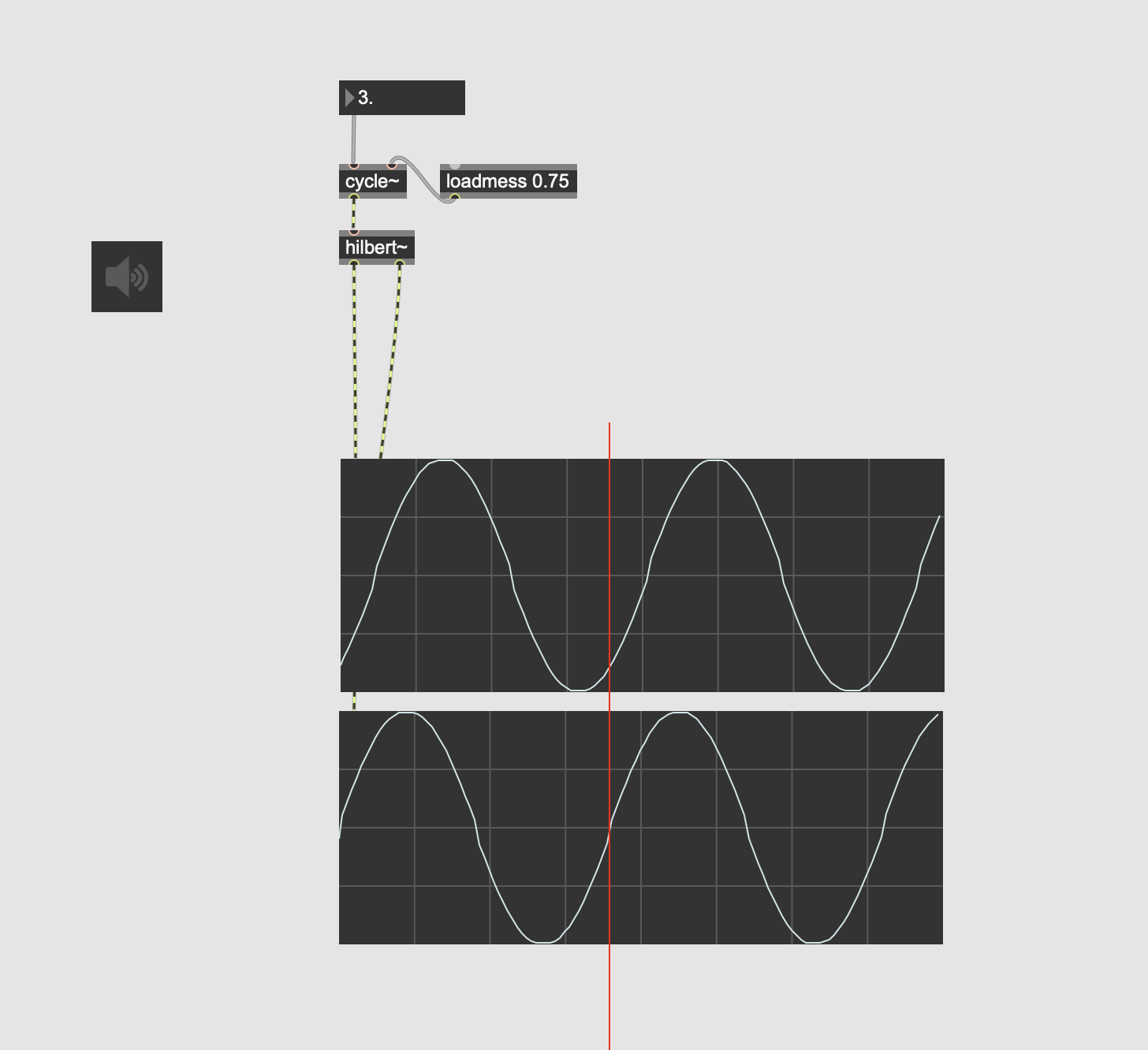

I guess the phase shift in [hilbert~] is done by a cascade of allpass filters. Like this it's difficult/impossible to achieved an exact 90 degree phase diff between both channels over the complete audio spectrum. your test freq is simply too low.
Whit Hilbert~ I see the 90 degree phase difference only with a frequency of around 5000 Hz. The rest seems to be different. I wonder what is the difference compared to a complex sine in which I get a true 90 degree phase difference.

Hi Federico,
that's not what I see... I see a 90 degree phase shift for most of the frequency spectrum with an increasing degradation towards the low and high ends, which is to be expected.
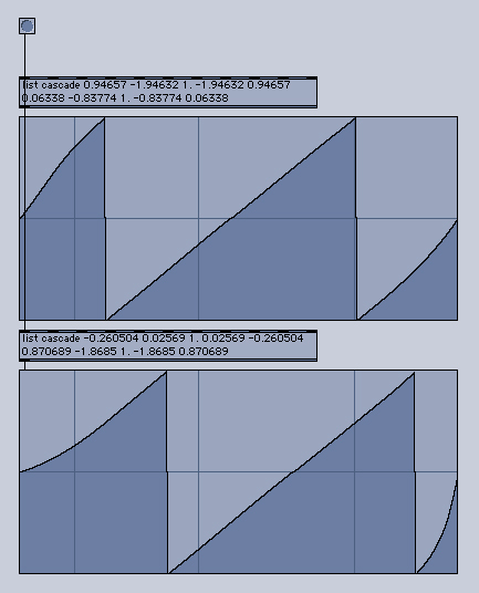
The attached patch is a quick attempt to highlight the 90 degree shift in the lower end of the spectrum. Let me know if it makes sense...

with an allpass/highpass design it cant be too perfect at the lower and higher end - and that is not required in practice.
and stay away from cosines and white noise as test tones, they fail in many situations. :)
... and your comparison patcher shows very well, that things are getting almost stable at around 8 Hz, just like expected.
and if you need more precision from hilbert~ over SR/4, feel free to upsample. :)
Ah ok, I got you now...
so - as it is shown in your patch - the answer is that there is no difference.
The Hilbert transform is a way to obtain the analytic signal from a real valued signal.
The analytic signal is a complex valued function without the negative frequency components.
The real and imaginary parts of an analytic signal are real-valued functions related to each other by the Hilbert transform. That's exactly what your patch is showing +/- some error due to the fact the Hilbert transform is implemented in Max/MSP as a cascaded allpass filter and therefore it is not perfect.
Due to the simplicity of a sinusoid the Hilbert transform is kind of superfluous in your example. As you have done, you can create a complex exponential simply by shifting the phase of the imaginary part. However with more complex signals the Hilbert transform becomes necessary if you need to obtain the signal's analytic representation, which facilitates many mathematical manipulations.
https://en.wikipedia.org/wiki/Analytic_signal
https://en.wikipedia.org/wiki/Quadrature_filter
https://en.wikipedia.org/wiki/Hilbert_transform
Hope this helps at least a little bit.
- Luigi

Luigi wrote: https://en.wikipedia.org/wiki/Quadrature_filter
"Quadrature"! 🙌 (this thread kept me trying to think of that term... but couldn't remember, kept thinking 'orthogonal' 😂 ...a similar term but not it..)
Thanks for this thread from me too! 🙏
Thanks a lot Luigi :-) ... thanks to all.
I tried a single sideband modulation with two complex sinusoids but it doesn't work so well. With hilbert~ it works better although there are some imperfections.
Here is a simple patch that I quickly put together to do some SSB testing.
Things that I have noticed:
1) The [hilbert~] filter as implemented in Max/MSP is indeed not very precise. In my frequency shifting tests I could hear artifacts that came from the filter not suppressing adequately all the negative frequencies. It would be handy to have a [hilbert~] transform filter where the order would be variable. That way it would be possible to trade computational cost for precision. I tried using the [cos~] object instead of [cycle~] to see if more accuracy in the way sine and cosine are computed would make any difference, but it doesn't.
2) Max/MSP comes with [cosx~] and [sinx~] externals, however it only features a [cos~] object, no [sin~] counterpart.
3) My patch version is almost identical to the [freqshift~] external, except I can generally hear more distortion in the output of [freqshift~]. For example when shifting a simple tone down to zero, distortion artifacts are clearly audible. (for example [cycle~ 220.] shifted down to -220 Hz)
Strange because in my experience when implementing an algorithm in code there are way more opportunities for accuracy and efficiency.
4) A DC-blocking filter on the output of the complex oscillator is a good idea.
5) The paper Roman sent is pretty cool.
I am done geeking out.
Thank you all.
- Luigi
Very useful text Roman...
Thanks for the patch Luigi, I hear more distortion in the out of freqshift~ too :-)