
WS2811 RGB control with Arduino and Max

Hi everyone,
I want to control 64 individual WS2811 RGB led units using toggles in max. I need to set the colour of the led and the brightness then send this data through the arduino using serial I think.
I have only ever worked with Arduino when receiving data, not sending, and only with standard led's, not RGB ones. Im not sure where to start with either the max side or the arduino coding, can anyone point me in the direction of any tutorials or examples please? I have researched a lot but cannot find any info for my specific needs. Its probably basic! But I am on a steep learning curve here personally.
Thanks in advance

You have to start with Arduino.
You need one of the libraries - either fastled or adafruit.
http://fastled.io/
https://github.com/adafruit/Adafruit_NeoPixel
If You get Arduino to control the leds,
than You can try controling it from max.
Thanks. I have the fastled library installed. I have run tests using the example code successfully. What I am not sure how to do is control it via max, in the arduino code it is a case of writing in the colour as a word and brightness as a number to change them, how would I control that from max? i'd need addressed integer values for each im guessing?
Could You upload the Arduino sketch that You want to use ?
Then I could tell better what to do with Max.
In simple words, You need to replaced fixed LED values
with data received from Max via serial.
And that depends very much on how You want to light leds,
using preprogrammed patterns, or individual LEDs colour change etc.
by 64 individual LED units You mean 64 single LEDs ?
or Stripes ?
Here is one example of setting Led color using 2 values coming from
Max serial.
First value is Led number, second RGB from a standard named web/HTML color code
see : https://www.computerhope.com/htmcolor.htm#color-codes
for example "1 Red" will light first led Red
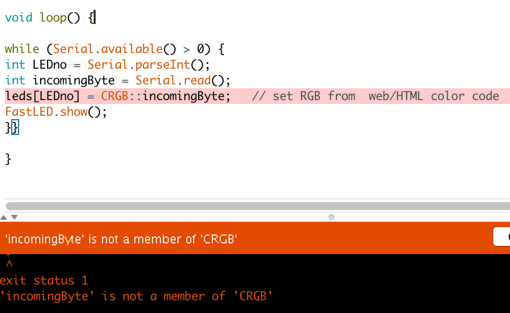
void loop() {
while (Serial.available() > 0) {
int LEDno = Serial.parseInt();
int incomingByte = Serial.read();
leds[LEDno] = CRGB::incomingByte; // set RGB from web/HTML color code
FastLED.show();
}}
// this is just loop portion of the sketch, don't forget to add
Serial.begin(9600); in void setup()
Max Patch:
Having some trouble compiling the arduino sketch, getting the error message 'incomingByte' is not a member of 'CRGB'
I am not using strips, I am using 64 individual leds. Each will be connected to a button eventually, I hope!
Thanks for your help
I see, means fastled.cpp won't accept changable string,
I don't have time to go debugging that,
but in the meantime let's try doing it with rgb values.
#include "FastLED.h"
#define DATA_PIN 3
#define CLOCK_PIN 13
#define NUM_LEDS 64
CRGB leds[NUM_LEDS];
void setup() {
FastLED.addLeds<WS2811, DATA_PIN, RGB>(leds, NUM_LEDS);
Serial.begin(9600);
}
void loop() {
while (Serial.available() > 0) {
int LEDno = Serial.parseInt();
int ledR = Serial.parseInt();
int ledG = Serial.parseInt();
int ledB = Serial.parseInt();
if (Serial.read() == '\n') {
leds[LEDno].setRGB( ledR, ledG, ledB);
FastLED.show(); }}}
Had some progress! I have made a simplified patch to just work with controlling 1 led.
Problem: It will turn on but the 1 0 0 0 message to turn to black/off doesn't work. I also tried with a close message suggested in another article but that also wont turn off so thinking maybe it is something to do with the arduino code side maybe?
Also, the units don't have a clock pin, only 5v GND and DI/DO... Could that be something to do with it?
Thanks
Ok... It does turn off, but there is a long delay between the toggle and the led turning off
Back to the CRGB::Red or other color - that can not be passed by serial port
simply because web colors are hardcoded, they are defined in colorpaletes.cpp.
So compiler throws an error if anything else is in that statement that does not match predefined colors.
Now to that delay - I don't know why should it behave so...
The patch I sent You was meant just to offer some sort of communication
between max and arduino.
I don't have such a led strip for testing here, so that part is left to You.
What if You try 1 10 10 10 instead of 1 0 0 0 or any other RGB combination ?
sending 4 ints is not a big deal, but You could try to increase baud rate
to 57600 , if so You have to do it both in arduino and max.
And let's add a bit of delay at the end of loop in arduino sketch.
#include "FastLED.h"
#define DATA_PIN 3
#define NUM_LEDS 64
CRGB leds[NUM_LEDS];
void setup() {
FastLED.addLeds<WS2811, DATA_PIN, RGB>(leds, NUM_LEDS);
Serial.begin(9600);
}
void loop() {
if (Serial.available() > 0) {
int LEDno = Serial.parseInt();
int ledR = Serial.parseInt();
int ledG = Serial.parseInt();
int ledB = Serial.parseInt();
if (Serial.read() == '\n') {
leds[LEDno].setRGB(ledR, ledG, ledB);
FastLED.show(); delay(50);
}}}
-----------------------
What do You mean by "close" message ?
to max serial object ?
That is not good, it just disconnects serial objects from aduino.
What arduino board are You using ?
You know that one should not have max serial object
and arduino IDE talking to the board at the same time ?
Hmm, I received mail, dated from 03.03. 2018 21:46 having following text :
----------------
I have still not figured this out. I have been told that the problem stems from the serial object not being able to send lists, only chars, so the message needs to be [ 1, 255, 255, 255,]
---------------
Did You delete that message ? Or is it somehow not been updated here yet ?
Anyway, I don't know who is being telling You what, but arduino sketch is
programmed to collect 4 ints coming on serial port, and set the
values as noted to LED number and 3 RGB values.
There is nothing wrong with it.
You have to debug the whole thing. Did You set both max patch and arduino to same baud ?
First make simple arduino sketch that turns one led on and off:
------------------------
#include "FastLED.h"
#define DATA_PIN 3
#define NUM_LEDS 64
CRGB leds[NUM_LEDS];
void setup() {
FastLED.addLeds<WS2811, DATA_PIN, RGB>(leds, NUM_LEDS);
}
void loop() {
leds[1].setRGB(255, 0, 0); FastLED.show(); delay(1000);
leds[1].setRGB(0, 0, 0); FastLED.show(); delay(1000);
delay(50);
}
----------------------
If that works ok than everything is ok with WS setup.
Than You have to check the serial communication.