
Gen~ no acumulator(integral symbol) feedback in patch

Hej Gen~ maxers. I am trying to figure out this schematic and how to translate it into gen~objects. I have prior experience with building a biquad filter, compressor and a reverb.
The schematic that I am using is figure 3 from this research paper (http://dafx13.nuim.ie/papers/44.dafx2013_submission_56.pdf) on making a digital model of the buchla lowpass-gate. The paper has links to the patch that was made for the research paper however every time I try to assemble and run all of the max, poly~ and gen~ code it crashes, but there is a link here if this is helpful;
So far I have managed to model something up that resembles the figur 3, however I ran into problems while I was making the model. (I probably want to do something which is not permitted in this type of domain but I don't know I am still just trying to wrap my head around gen~) My problem is that the feedback elements (a2, b2, b3, d1 & d2) cannot connect with my [integral] or [d/dt] nested gen objects in the gen~ patcher.
I have tried to compensate for this by adding the history object so that there will be -1 sample delay that allows the feedback to happen, but of course this does not work!
- I don't know why I can't connect these feedbacks with the [integral] or [d/dt], what is the reason behind this?
- Is it possible to run the code that was used for the paper without having it crash all of the time?

A few tips:
- I suggest while working out an algorithm, just use a simple maxpatcher and embedded gen~ (rather than a max project, gendsp file, etc.). The experience will be more fluid and you can restructure to project/gendsp etc. later.
- Look at the gen~.biquad.maxpat example included with Max for an example of how to write a biquad.
- gen will not allow any kind of feedback path without a [history] or [delay] object, because that would create an infinite loop and crash the machine. This is normal for DSP programming in general. In signal diagrams a single-sample delay is usually represented as Z^-1; in gen~ it is [history].
- gen won't allow feedback around a subpatcher (a sub-[gen]) without a [history] object *outside* of the subpatcher. For a circuit as simple as this one you might find it easier to not use subpatchers at all.
- For a basic integrator, you can use [+=] or [accum] (they are the same object, just different names). That might help simplify the integral circuit.
- For a basic differentiator you can use [delta]. This gives you the slope per sample of the input, which is the discrete df/dt for a given t = 1/Fs. That might help simplify the DFDT circuit.
Hopefully that makes things a lot clearer!
Also I note that in the conclusion of the paper it states "The resulting combined model was implemented for real- time use in Max/MSP and Gen~." -- did you try contacting the authors to ask if they would share it?
This is what I get if I try to imlement the d/dt and integral structures from the paper:
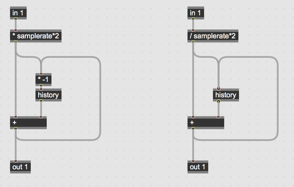
The authors also note in the paper (p3) "The primary problem when discretising a filter via this approach is the delay-free loops that are formed if the discrete integrator blocks have a delay-free path through them" -- which sounds like the problem you are having. The diagram on p3 can't be implemented in discrete terms as it is shown, and they are acknowledging this in the text; they discuss different approaches for how to solve that over the course of p4.
Also there's some errata you might want to know about: http://www.dangelo.audio/docs/errata_buchlalpg.pdf

Hey! I knew Julian. :-)
Anyway, there are demo Max patches available in the source/ folder of the directory linked in the OP in case that's helpful.

Hi - for anyone interested in the intriguing subject of coding analog circuits here is an updating of the links discussed in this chain:
The paper "A digital model of the Buchla lowpass-gate"
the errata:
and the Max/Msp implementation: