
Serial issues, Line6 Floorboard-Arduino-Max8- ?midi controller? amplitube/tonex/protools/etc?

I found a wicked project online to connect a line 6 floorboard ( guitar amp controller) to an arduino. The arduino then creates a serial output string of three values.
one 0-8 and two 0-255 values in the format: 0 240 169
This represents 9 momentary buttons and two variable expression pedals.
The board also has a handful of LED's and three 7 segment displays
The project I found also came with "max7 patches".
I am honestly quite unfamiliar with the software but am finding my way around.....stumbling along.
I have ensured the serial settings are correct in both the code and the max project.
long story short:
I havethe floorboard talking to the arduino no issue. Arduino IDE shows communication in the serial buffer.
Same results in putty.
Max 8 continues to say specified port not available.
Nothing else is using that port.
End goal is to use these inputs to trigger midi events in other software such as Tonex, Amplitube, Protools, Logic etc...
clearly the arduino side is working. just need something to process it on the pc and convert to midi. Any input is appreciated.
MAX FILES ATTACHED BELOW
Arduino Nano Code:
#include <digitalWriteFast.h>
/**
* Arduino interfacing with the Line 6 Floorboard
*
* Thanks to Mark Lavelle for deciphering how this floorboard works and publishing on his website.
* Go here for the document: http://harmonicappliances.com/floorboard/floorboard.html
*
* The following is a description of how to make the connection to the floorboard
* (which I copied from the website linked above, because I am lazy as hell.)
*
* ==============================================================
* The POD & Floor Board use standard "Category 5" network cables for connection.
* The connectors on these cables (and the receptacles in the POD and Floor Board) are known as RJ-45s.
* They're just like standard phone jacks, but with 8 pins.
*
* The pin numbering I'll use for RJ-type jacks starts at 1 and goes from left to right
* looking into the receptacle (the female socket on the POD or Floor Board)
* with the locking tab slot on the bottom, like the diagram below.
* "Standard" or not, that's the numbering I'll be using here.
* ==============================================================
*
* And here is a very lame ASCII interpretation of the connection drawing.
* (Again, for details visit that website linked above.)
*
* 1: Ground
* _________________ 2: Wah
* | = = = = = = = = | 3: Ground
* | 1 2 3 4 5 6 7 8 | 4: Volume
* |_____ _____| 5: LEDs
* |_____| 6: Switches
* 7: +5V
* 8: +5V
*
* So, what we'll be doing is connectiong those lines directly to our arduino.
* And, basically, besides the power lines, we'll only be using 3 analog and 1 digital
* pins which is Awesome!
*
* Analog pins will be 3, 4 and 5 for switches, wah and volume respectively.
* The LED output will go to digital pin 8 (but it can be any from 8 to 13 since I'm using a method I stole
* from the internet -don't remember where, sorry- for writing faster than digitalWrite in which all digital
* output is written to all those pins.)
*
* A quick tip:
* Take a Cat5 cable and cut one end, just to lose the connector, then strip like 1/4" from each wire.
* You can easily use this wires with a protoboard to connect with your arduino, and use the connector in
* the other end and plug your floorboard.
*/
// This are the analog pins, used for the switches and expression pedals.
const int pinSw = 3; // to pin 6 in the RJ45 connector
const int pinWah = 4; // to pin 2 in the RJ45 ...
const int pinVol = 5; // to 4 in ...
const int pinLED = 8;
// This constants are the bit positions for each of the LEDs.
const int DIST = (8*0)+7;
const int DOWN = (8*1)+7;
const int POINT = (8*2)+7;
const int TAP = (8*3)+7;
const int WAH = (8*3)+6;
const int SEL = (8*3)+5;
const int DRV = (8*3)+4;
const int CHD = (8*3)+3;
const int CHC = (8*3)+2;
const int CHB = (8*3)+1;
const int CHA = (8*3)+0;
// I made a fancy presentation and use this variable to run it only the first time I engage the thing.
bool presentation;
// We use these to remember what input we had in the previous read.
byte swValue = 0;
byte volValue = 0;
byte wahValue = 0;
// We have to move all the foot to calibrate the wah
int readBounds[2][2] = {{420,780},{380,780}};
// Smoothing the expression pedals
const int numReadings = 6;
// We use arrays of 2 because that's the number of variable resistors we have
int readings[2][numReadings]; // the readings from the analog input
int readIndex = 0; // the index of the current reading
int readTotal[2]; // the running total
int readAverage[2]; // the average
// We use these to eliminate bouncing (stolen from here: https://www.arduino.cc/en/Tutorial/Debounce)
int buttonState; // the current reading from the input pin
int lastButtonState = LOW; // the previous reading from the input pin
// the following variables are unsigned long's because the time, measured in miliseconds,
// will quickly become a bigger number than can be stored in an int.
unsigned long lastDebounceTime = 0; // the last time the output pin was toggled
unsigned long debounceDelay = 50; // the debounce time; increase if the output flickers
// The values of each LED are stored here.
byte leds[] = {0,0,0,0};
// This is the character map for the LCD display
byte digit[255];
void initChars() {
digit['A'] = B11101110;
digit['B'] = B00111110;
digit['C'] = B10011100;
digit['D'] = B01111010;
digit['E'] = B10011110;
digit['F'] = B10001110;
digit['G'] = B11110110;
digit['H'] = B01101110;
digit['I'] = B00001100;
digit['J'] = B01111000;
digit['k'] = B01001110;
digit['L'] = B00011100;
digit['M'] = B10101000;
digit['N'] = B00101010;
digit['O'] = B00111010;
digit['P'] = B11001110;
digit['Q'] = B11100110;
digit['R'] = B00001010;
digit['S'] = B10110110;
digit['T'] = B00011110;
digit['U'] = B01111100;
digit['V'] = B00111000;
digit['W'] = B01010100;
digit['X'] = B01011110;
digit['Y'] = B01110110;
digit['Z'] = B10011010;
digit['-'] = B00000010;
digit['_'] = B00010000;
digit['0'] = B11111100;
digit['1'] = B01100000;
digit['2'] = B11011010;
digit['3'] = B11110010;
digit['4'] = B01100110;
digit['5'] = B10110110;
digit['6'] = B10111110;
digit['7'] = B11100000;
digit['8'] = B11111110;
digit['9'] = B11110110;
}
void sendPulses() {
for (int i = 0; i< 32; i++) {
// We always send one on and one off for each led or display segment.
// The duration of each pulse tells the floorboard if the led is on or off.
byte time1 = ((leds[i/8]>>(i%8))&1) ? 1 : 5;
byte time2 = 6 - time1;
digitalWriteFast(pinLED, HIGH);
delayMicroseconds(time1);
digitalWriteFast(pinLED, LOW);
delayMicroseconds(time2);
}
}
// Sets the char chr in the pos position of the 3 char display
void setChar(char chr, int pos) {
leds[pos] = (leds[pos] & 1) | digit[chr];
}
// Update a LED
void writeLed(int pos, bool val) {
int byt = floor(pos / 8);
int shft = pos % 8;
byte msk = ~(1<<(7-shft));
leds[byt] = (leds[byt] & msk) | (val<<(7-shft));
sendPulses();
}
// Puts the first 3 chars of the string on the 3-digit display
void writeScreen(String text) {
for(int i; i<3; i++) {
if (i+1>text.length()) {
setChar(0,i);
} else {
setChar(text.charAt(2-i),i);
}
}
sendPulses();
}
// My fancy 3-digit-7-segment-only-numbers-and-some-letters-marquee function
void typeText (String str, int repeat, byte spd) {
String newText = " " + str + " ";
newText.toUpperCase();
int ms = map(spd, 0, 255, 1000, 50);
for (int i = 0; i < repeat; i++) {
for (int chr = 0; chr < str.length()+3; chr++) {
String segment = newText.substring(chr, chr+3);
writeScreen(segment);
Serial.println(segment);
delay(ms);
}
}
writeScreen(" ");
}
void setup() {
// Initialize fast digital write, needed for sending the LED pulses.
DDRB = 255;
pinModeFast(pinLED, OUTPUT);
initChars();
presentation = 1;
Serial.begin(9600);
// initialize all the readings to 0:
for (int thisReading = 0; thisReading < numReadings; thisReading++) {
readings[0][thisReading] = 0;
readings[1][thisReading] = 0;
}
}
// All switches use the same analog input but with different resistance values,
// so we have a different voltage for each switch
byte buttonValue(int value) {
if (value < 50)
return 8; // TAP BUTTON
if (value < 130)
return 7; // CHANNEL SELECT
if (value < 250)
return 9; // WAH
if (value < 350)
return 3; // CHANNEL A
if (value < 430)
return 4; // CHANNEL B
if (value < 500)
return 5; // CHANNEL C
if (value < 600)
return 6; // CHANNEL D
if (value < 780)
return 10; // PRESET ( UP + DOWN)
if (value < 830)
return 2; // UP
if (value < 880)
return 1; // DOWN
return 0; // NO BUTTON PRESSED
}
// I made this function at the begining for testing the LEDS, but I liked so much that
// I left it here and use it as part fancy presentation.
void test(bool val) {
int dl=80;
writeLed(DIST, val);
delay(dl);
writeLed(DOWN, val);
delay(dl);
writeLed(POINT, val);
delay(dl);
writeLed(TAP, val);
delay(dl);
writeLed(WAH, val);
delay(dl);
writeLed(SEL, val);
delay(dl);
writeLed(DRV, val);
delay(dl);
writeLed(CHD, val);
delay(dl);
writeLed(CHC, val);
delay(dl);
writeLed(CHB, val);
delay(dl);
writeLed(CHA,val);
}
byte parseFromMax(byte data) {
// Digits in max are represented with their ASCII value, the floorboard uses a lcd segment
// map described in the document linked in the description at the top of this file.
return digit[data & ~(128)] | data>>7;
}
void badassPresentation() {
test(1);
test(0);
typeText(" 420_ ", 1, 220);
test(1);
test(0);
}
int smooth(int pos, int value) {
value = constrain(map(value, readBounds[pos][0], readBounds[pos][1], 0, 255), 0, 255);
readTotal[pos] = readTotal[pos] - readings[pos][readIndex];
readTotal[pos] += value;
readings[pos][readIndex] = value;
readAverage[pos] = readTotal[pos] / numReadings;
return readAverage[pos];
}
void loop() {
// My badass presentation!!!
if (presentation) {
presentation = 0;
badassPresentation();
}
// Start reading the analog inputs.
byte readSw = buttonValue(analogRead(pinSw));
byte byteWah = smooth(0,analogRead(pinWah));
byte byteVol = smooth(1,analogRead(pinVol));
readIndex = readIndex + 1 == numReadings ? 0 : readIndex + 1;
// And again, All of this debouncing stuff was taken from here:
// check to see if you just pressed the button
// (i.e. the input went from LOW to HIGH), and you've waited
// long enough since the last press to ignore any noise:
// If the switch changed, due to noise or pressing:
if (readSw != lastButtonState) {
// reset the debouncing timer
lastDebounceTime = millis();
}
if ((millis() - lastDebounceTime) > debounceDelay){
// whatever the reading is at, it's been there for longer
// than the debounce delay, so take it as the actual current state:
// if the button state has changed
if (readSw != buttonState) {
// only toggle the LED if the new button state is HIGH
buttonState = readSw;
}
}
// save the reading. Next time through the loop,
// it'll be the lastButtonState:
lastButtonState = readSw;
// Now if somenthing changed since the last time we proceed to process the input data.
if ((byteVol != volValue) || (byteWah != wahValue) || (buttonState != swValue)) {
// update the globals, to remember the nex time.
wahValue = byteWah;
volValue = byteVol;
swValue = buttonState;
// With this I can send the three input bytes to the serial port, which i happen to read back there on Max7
Serial.print(swValue);
Serial.print(" ");
Serial.print(wahValue);
Serial.print(" ");
Serial.println(volValue);
delay(20);
}
// Check if we have input in the serial port
if (Serial.available()) {
// Led info is represented in 4 bytes
char buf[4];
Serial.readBytes(buf, 4);
leds[0] = parseFromMax(buf[0]);
leds[1] = parseFromMax(buf[1]);
leds[2] = parseFromMax(buf[2]);
leds[3] = buf[3];
// Finally send all these bits as a pulse train to the floorboard.
sendPulses();
}
}

You forgot to provide main infos which could help to solve your problem.
All that arduino code does not matter at all.
At the end it just sends few values to serial port.
1- OS
2- Max version
3- exact Arduino model, (there are loads of different nano boards)
which also includes type of USB - Serial chip.
There were reports about max 8.5.7 faillig to receive data
from serial port, but your problem is board not getting recognised.
That might be even caused by max patches that were made
on oder Mac Max version and do not work on Windows at all.
Do you know how to deal with serial port object in max?
Windows 10 version 10.0.19045
max version 8.5.7
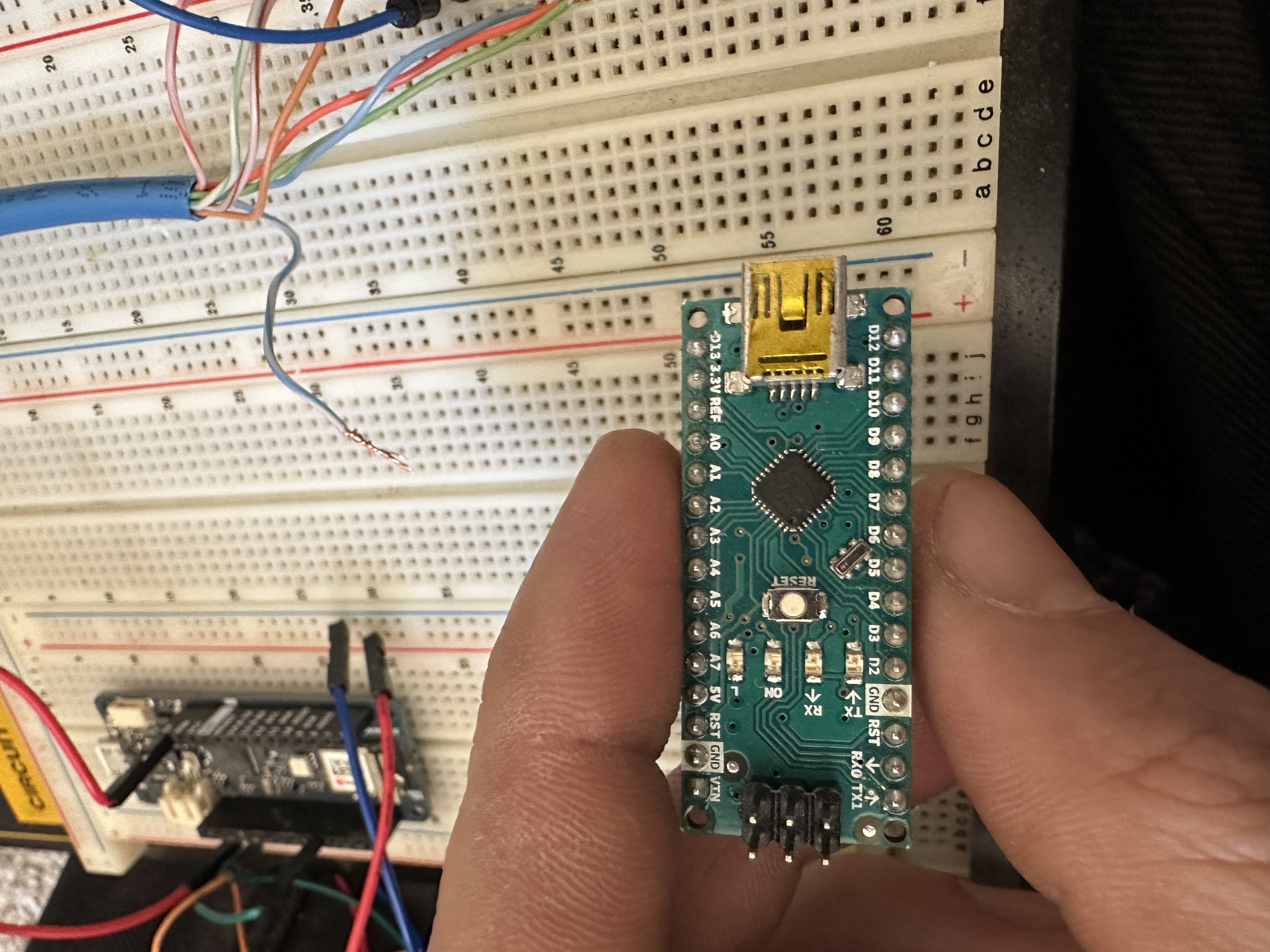
To my knowledge it's an original Nano board form 10 years ago with Mini B usb .
Box says A000005
SKU is 8058333490342
Printing on the board says
arduino nano
arduino cc
S011RU94v-0
ROHS compliant
designed and assembled in Italy
Attached are the max patch files provided to me with the arduino code.
I have figured out how to modify the serial parameters (baud rate etc) in the patch.
Just installed max three days ago. I am unfamiliar with the work flow and how to use this software.
If it wont work on windows then i need to go back to the drawing board for this part.
Here are a couple pictures of the nano board
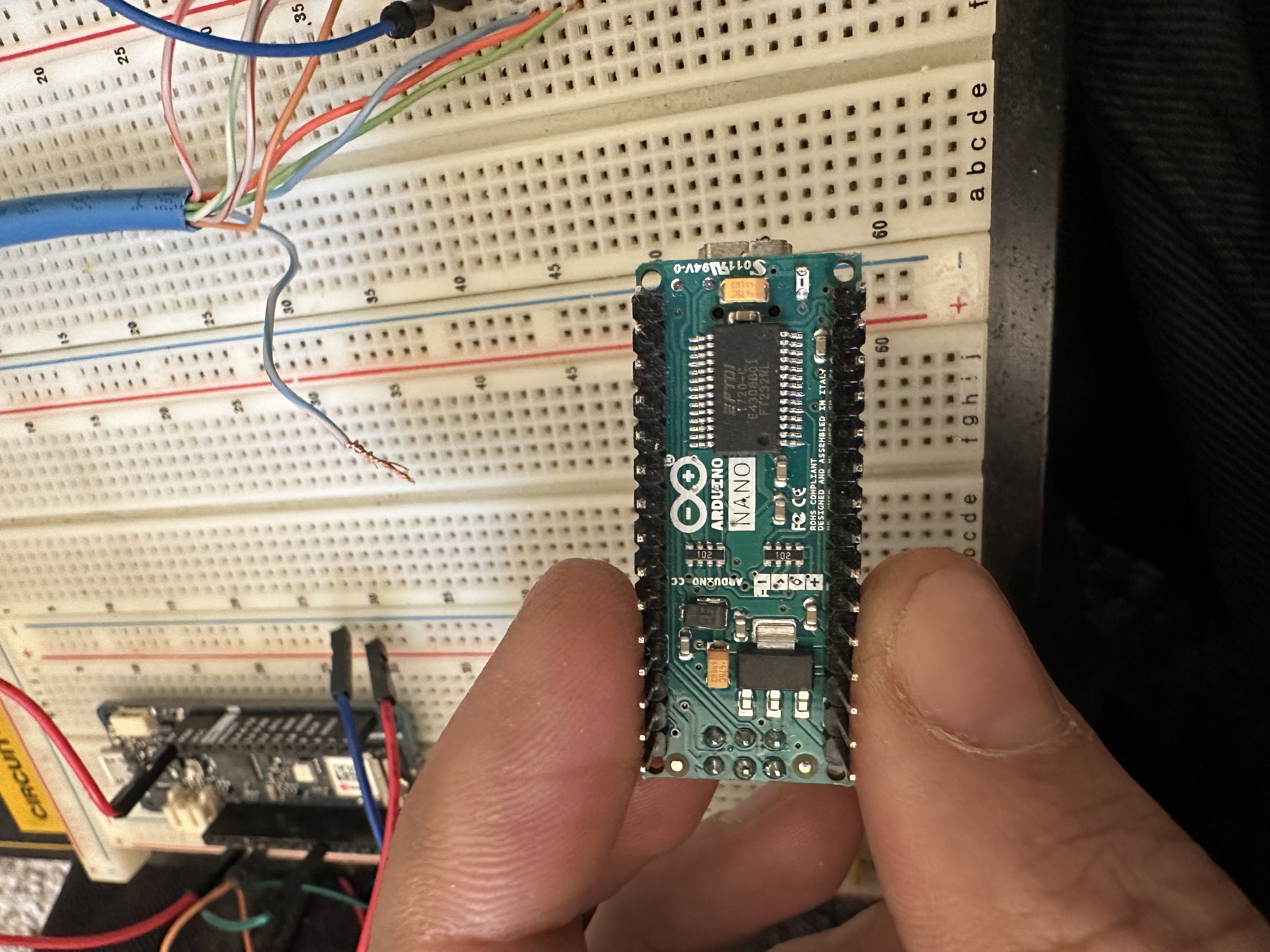
Pic of the top.
ftdi usb-serial nano with probably 328p should not be a problem.
but there were reports max 8.5.7 on Mac has problem
with serial devices, maybe also on windows ?
I will check that later today with similar board on W10 and
let you know.
for you it would be better to make simplest serial send
sketch to test communication.
if you want I could post such example
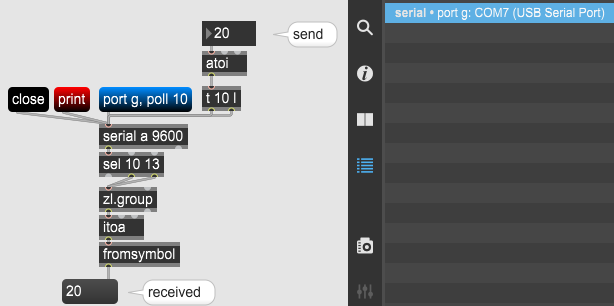
ok just made a short test on fresh installed WIN 10, Max 857
and old nano board with ftdi usb serial, just like your nano.
Had to install ftdi drivers first.
It works ok.
You just need to print list of serial devics, and then
send message to serial, like port g, poll 10
in case your nano gets that port assigned.
you can try this simple loopback test:
String inString = "";
int TEST;
void setup() {Serial.begin(9600);}
void loop() {if (Serial.available() > 0) {int inChar = Serial.read();
if (isDigit(inChar)) {inString += (char)inChar;}
if (inChar == '\n') {TEST = inString.toInt();
Serial.println(TEST); inString = ""; }}}
max patch
Ok, that example worked

Hi I have one of these floorboard and I want more information on this. Do I need an arduino to make it work?? Can I just connect it to a Ethernet/usb external usb?? And configure or anything??