Husserl tutorial series (4). Anti-Aliasing Oscillators
This tutorial was originally a popular blog on https://yofiel.com, which has since been redesigned and contains other things. Download examples are at the end of the page. All the tutorials in this series:
Designing a good LFO in gen~ Codebox: https://cycling74.com/forums/gen~-codebox-tutorial-oscillators-part-one
Resampling: when Average is Better: https://cycling74.com/forums/gen~-codebox-tutorial-oscillators-part-2
Wavetables and Wavesets: https://cycling74.com/forums/gen~-codebox-tutorial-oscillators-part-3
Anti-Aliasing Oscillators: https://cycling74.com/forums/husserl-tutorial-series-part-4-anti-aliasing-oscillators
Implementing Multiphony in Max: https://cycling74.com/forums/implementing-multiphony-in-max
Envelope Followers, Limiters, and Compressors: https://cycling74.com/forums/husserl-tutorial-series-part-6-envelope-followers-limiting-and-compression
Repeating ADSR Envelope in gen~: https://cycling74.com/forums/husserl-tutorials-part-7-repeating-adsr-envelope-in-gen~
JavaScript: the Oddest Programming Language: https://cycling74.com/forums/husserl-tutorial-series-javascript-part-one
JavaScript for the UI, and JSUI:<a href="https://cycling74.com/forums/husserl-tutorial-9-javascript-for-the-ui-and-jsui"> https://cycling74.com/forums/husserl-tutorial-9-javascript-for-the-ui-and-jsui
Programming pattrstorage with JavaScript: https://cycling74.com/forums/husserl-tutorial-series-programming-pattrstorage-with-javascript
Applying gen to MIDI and real-world cases. https://cycling74.com/forums/husserl-tutorial-series-11-applying-gen-to-midi-and-real-world-cases
Custom Voice Allocation. https://cycling74.com/forums/husserl-tutorial-series-12-custom-voice-allocation
The Pulse Aliasing Problem
To summarize the mathematical technicalities in layman terms, audio pulse waves suffer from particularly bad aliasing distortion, because they have sudden vertical transitions between the top and bottom output rails. At different frequencies, the exact locations of the transitions should occur at varying points between two digital audio clock cycles, but the digital clock can only place the transitions on its clock boundaries. The misalignment with the audio clock samples adds dissonant distortion artifacts to the sound across the entire frequency spectrum (and not just at the spectra's upper end, where the signal is more obviously distorted by cycle clipping). So while musical digitization has done well to eliminate the hiss and noise of the old analog oscillators, it has added a new type of signal distortion, referred to as 'aliasing.'
The same aliasing problem exists to a significant extent for sawtooth waves, which have one complete vertical transition, and to a lesser extent in triangles and other waves with linear slopes; and to a lesser extent for all signals which are not pure sine waves. But it is less apparent--even for sawtooths--because sawtooths have complex harmonics, whereas square waves in particular should ideally have only a pure set of odd harmonics. As a consequence, the aliasing distortion in square waves is particularly audible as either bright overtones, or as dissonant harmonic content.
Historical Solutions
To counteract this distortion, older anti-aliasing techniques (referred to as BLEPs, miniBLEPs, and BLITs) add a tiny wavelet to the fundamental signal, with varying frequency, wavelength, and wavelet length depending on the oscillator frequency. The addition intends to counteract ugly aliasing overtones by adding exactly the same tones in opposite phase--in effect, they are extremely complicated forms of noise cancellation.
The following scope freeze illustrates how the anti aliasing appears for one such conventional technique, creating what is often called a 'band-limited" wave. The spikes appear to be distortions visually, but in fact they counteract the audio distortion and create a better sound.
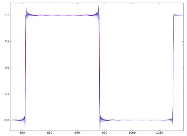
Sadly, the little wavelets need a great deal of precision and accuracy, because if they do not exactly duplicate the aliasing overtones in opposite phase, they add noise rather than remove it. Furthermore, the exact required wavelet can vary continuously, depending on the algorithm and desired quality, because the pulse transition points vary in specific locale between the audio clocks. Thus their calculation in real time is not only complex, and varies depending upon the wave frequency, but also may need to be repeated for each and every wave cycle, significantly reducing performance.
For this reason, digital emulations of analog oscillators usually precalculate the antialiasing waves over some span of time for a large number of different frequencies, and store all of the wavesets in a massive wavetable, with the unfortunate side effect of making smooth contour modulations virtually impossible beyond the simplest cases; and creation of the wavetables themselves is an immense amount of work, especially as different wavesets must be built for different frequency bands that may be overlaid or divided up in different ways, often resulting in varying quality across the frequency range. Extensive technical debates still continue, to this day, as to the best way not only to create the wavelets, but also how to design the wave sets.
The New Way: PTRs
Thankfully, a technique has emerged over recent years that requires far less real-time processing, referred to as Polynomial Transition Region (PTR) antialiasing. With this comparatively new technique, instead of adding a tiny, partial wavelet just before the transition from high to low, or low to high (the 'transition region'), a polynomial curve is added to the entire wave with characteristics that intend to shape the transition region and, due to the polynomial coefficients, intend to leave the rest of the wave basically unaffected. By adding a little bit of a curved sloped to the sudden transition, aliasing overtones can be significantly reduced.
The PTR method greatly reduces CPU load, because the polynomial is far simpler to calculate than the older antialiasing algorithms, so it can easily be calculated in real time. Hence PTR enables generalized width modulation without precalculating massive numbers of wave sets. Perhaps even more significantly to many, PTR is also well suited to frequency-modulation (FM) applications. This is because, in older antialiasing techniques, the wavelets added to the fundamental wave also create unwanted harmonics when, in FM, the carrier and modulator are combined to make a different frequency. On the other hand, with PTR, the slight or steep curve added to the fundamental signal can be a sine wave or similar, which unlike the wavelets for older techniques, does not add vastly varying amounts of dissonant signal content when the fundamental frequency modulates another. PTR antialiasing can therefore create far more pure results when the oscillator is used for FM, depending on the design of the transition polynomial.
Even Newer: EPTRs
The two main issues for PTR algorithms are, first, that the polynomial still adds some slope to the rest of the signal outside the transition region; and second, the polynomial may not add so much processing as older antialiasing techniques, but it still can increase CPU significantly, especially if it contains transcendentals.
So even more recently, a new technique called Efficient, or Enhanced, Polynomial Transition Region (EPTR) has further reduced the CPU requirements for antialiasing. With EPTR, the additional processing required for the polynomial is only activated during the transition itself. This results in a tiny amount of additional processing for a conditional test while the wave is being generated to find the transition region, but it is far less than adding a polynomial to the entire curve, because the transition region only needs to be, at most, a small number of audio clocks before and after the transition in a pulse wave, or even just a single clock cycle, depending on your authority\'s opinion. So during the tiny transition region, a polynomial is applied to add a slight curve to a very small number of samples, and the rest of the wave is unaffected.
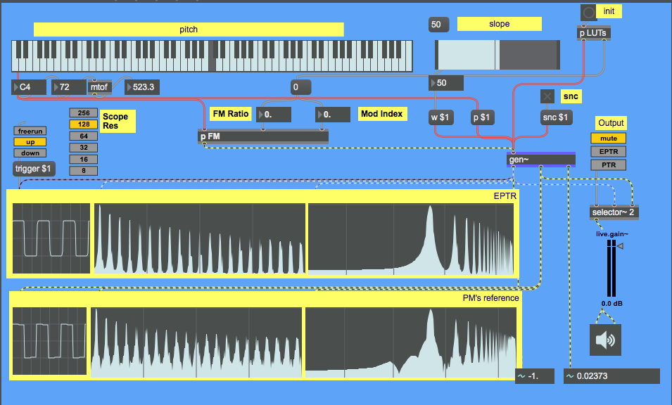
Additionally, for polyphonic applications beyond the dry numeric world of pure maths, oscillators typically run at different frequencies, so the transitions for multiple oscillators occur at different points in time, spreading out the overall processing and making the effective CPU load even smaller. also, of course, EPTR antialiasing is also well suited to width modulation and FM. This is a detailed spectral response of Yofiel's current EPTR (red) compared to the MSP~ ~rect object for a square wave at 1kHz (blue).
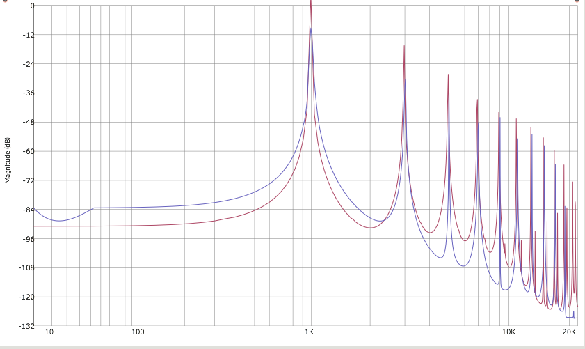
As you can see, there is virtually no difference in the harmonic response curves, but Yofiel's EPTR oscillator is calculated in real time without using wavetables or BLEPs/BLITs, with virtually the same CPU as for a raw aliased square wave; and Yofiel's oscillator is capable of FM without aliasing artifacts--as well as FM feedback, which the MSP~ version cannot do, because FM feedback requires single-cycle frequency changes, and the MSP~ oscillator has to operate on blocks of signal data.
You may also notice that the EPTR waveform has slightly higher gain. But I didn't match the gain of the two oscillators for this graph, because the EPTR is actually more accurate in this respect. With conventional antialiasing, the wave cannot swing entirely between the rails, as it needs some extra space above and below the pulse wave for the antialiasing wavelets (in order to keep the conventional antialiased-wave's maximum output between -1 and +1). The EPTR oscillator, on the other hand, doesn't need that headroom for its antialiasing, and if its the gain is reduced below what it should be, to correspond to the older antialiased version, the signal/noise ratio for the EPTR is even better.
Choosing the Polynomial
The new debate therefore shifts out of the extremely complicated wavelet maths and wavesets to the comparatively simple choice of the best polynomials and transition regions. In this design, the transition's slope is determined by making half a cosine wave, exactly swinging between 1 and -1, over six samples at all frequencies below one eighth the sample rate. The first and last samples are either 1 or -1, so the conditional test to find the transition region is set up to skip the first and last samples and find the four samples between them, reducing the amount of polynomial processing by a further third.
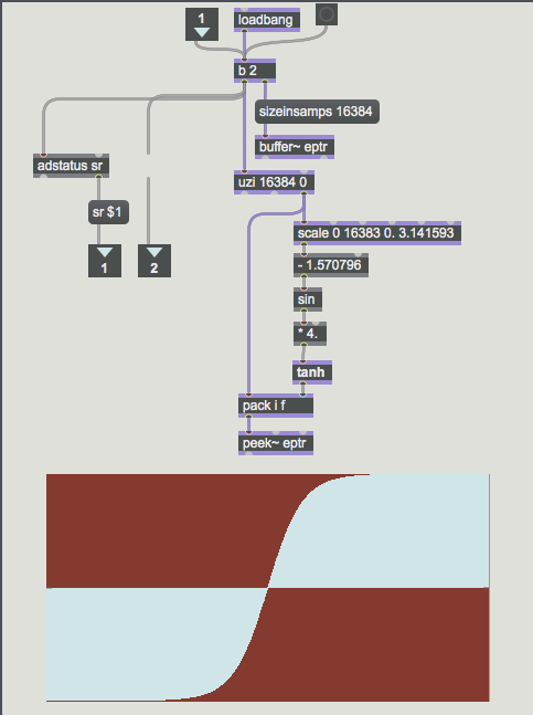
The sine values are then transformed into a much steeper curve by transforming the sine wave with a tanh function. The inverted wave is applied to the pulse transition in the opposite direction. Hence there is a maximum of 8 polynomial calculations in each complete audio wave cycle. The effect of the tanh function on the sine wave is to spread the sparse number of samples on each transition towards the -1/+1 rails, and to steepen the curve. With only four points between the rails, the point density is too sparse to visualize the curve, so the following figure shows the transformation with many more points.
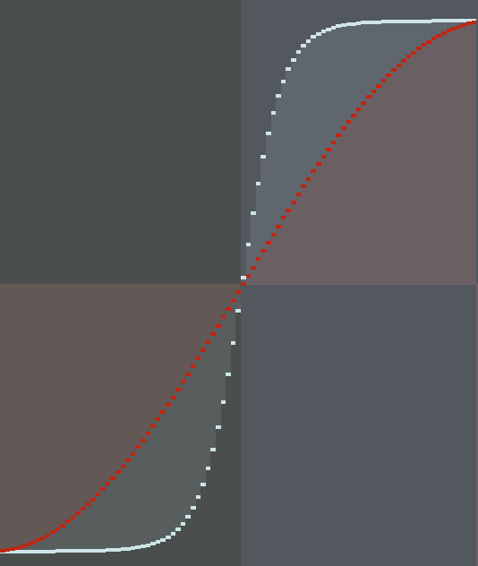
Now thinking additively of the original wave the added curve to the transition, the transformation of the transition curve with a tanh function turns the sine wave into a very steep parabolically shaped pulse, occurring twice during each of the fundamental's wave cycles, with an *extremely* narrow pulse width. So there may be some very slight harmonics, but as the tanh curve is very steep, and the transition is rare compared to the fundamental over most of the audible range, the amplitude of the added harmonics are extremely low. At higher fundamental frequencies, this design reduces the width of the transient window, but the crosspoint was chosen for other reasons than eliminating more harmonics, as described below.
I experimented with a range of different transition window sizes, and also with adjusting the slope according to the fundamental frequency, which theoretically would spread any noise from the transition curve harmonics during polyphony. That second enhancement makes the polynomial much more complicated, and after much experimentation, I could not find any significant enough improvement to warrant its addition. I also tried adding a small random variation to each transition slope, which would probably annoy pure mathematicians, who tend to prefer the purity of calculus over noise theory and practical physics. But this method did improve bandwidth in later modem designs, so I tried it. And actually, adding random variation to the slope can noticeably improve the results at the very top of the pitch scale, as the random variation spreads the alias harmonics into attenuated hiss, rather than adding some fixed aliasing frequency. For this release, I still decided on the simpler version here, rather than including this enhancement, more because of aesthetic reasons outlined below.
First EPTR Example
Moving on from the harmonic theory and practice, then the first download on this page is for a PWM pulse wave oscillator using the above outlined EPTR technique. The input is a ramp, which permits phase modulation and sync. To further reduce processing load, the polynomial algorithm (which includes the several transcendental functions as explained above) is precalculated over the required range at initialization, then stored in a Look-Up Table (LUT) for use during audio runtime. And the polynomial was transformed so that, for the transition curve itself, only one multiply, one add/subtract, and one table lookup is required.
The result easily outperforms existing implementations in both performance and quality, for frequencies up to MIDI F7. Above that frequency, the number of audio clock cycles in each wave cycle were too small to permit calculation of the transition region points in one audio clock cycle. The implementation therefore upsamples the oscillator to run at three times the audio clock cycle, but only when the wave frequency is high enough to benefit from it, and to note in defense of the additional processing, the frequency at which upsampling starts is much higher than can even be obtained by a non-antialiased pulse at all.
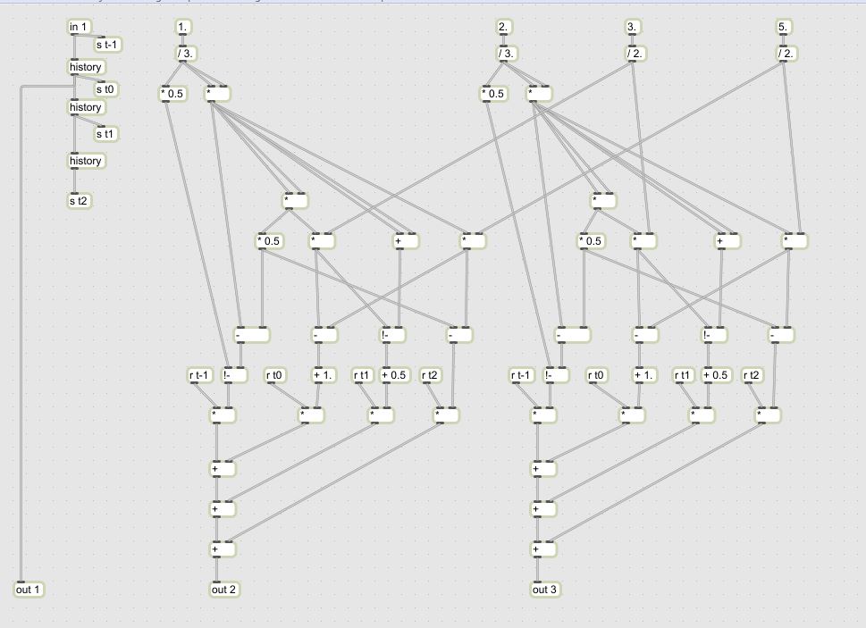
As the input is a ramp, standard upsampling techniques (such as spline interpolation) do not work, as they remove the 1->0 transitions at the end of the ramp. Hence a custom routine simply interpolates the linear ramp during its rising phase, and calculates the falling transition points using phase history, yielding absolutely precise upsampling.
Note: there's been much more interest in this part of the design than I expect, so here is a picture of how the same upsampling of the phase accumulator can be done in gen~ objects rather than code.<p>
There was also the same problem with traditional downsampling techniques. As the output is a pulse, conventional downsampling interpolation flatten the pulse more into a sine wave, removing the design intent entirely. A second custom routine therefore attempts to preserve pulse characteristics based on some simple standard PCM compression theory (that was actually developed in Japan, by Oki Electric, for digital telephony). The upsampling increased the dynamic range an additional octave, with relatively low CPU overhead compared to other techniques.
At very high frequencies, EPTR provides an additional benefit. When approaching Nyquist (half the audio clock frequency), the curve which EPTR puts in the waveform around the transition point does not reach the opposite pole before the oscillator switches direction again, so the signal no longer swings completely between -1 and +1, but is attenuated. After DC blocking, this reduces the amplitude of the oscillator output very rapidly with increasing frequency, as in effect the EPTR polynomial is acting similar to a brick-wall low-pass filter. It is possible to adjust the curve coefficients to increase this effect, but doing so also increases the distortion before and over the relatively small frequency band where the amplitude reduction starts to take effect. So the next portion of this project will be to design a simple low-pass EQ, set at a high frequency, to prevent Nyquist distortion over this amplitude reduction range (spanning about half an octave at the top of the effective frequency range).
An additional improvement could be also be made for narrow pulses at high frequencies, which reduce in amplitude for the same reason. The simple solution would be to restrict the PWM duty-cycle range at higher frequencies. Currently the design permits 5% to 95% duty cycle (upward and downward pulses are both possible), and in fact it could work with even narrower pules at lower frequencies, but an additional issue arises that the energy in the signal becomes extremely low, attenuating the output signal too much to be of general use. Currently I am undecided whether to add a gain increase to lower frequencies, so that narrower pulses have the same effective amplitude, to increase the PWM range to 15~~99% as saws possible with the best analog synthesizers, because it would again require nonlinear functions which would increase processing overhead. A simpler solution for high frequencies could be to rescale or clip the PRM range between, say, 25% and 75% when the frequency is above 1/4th or 1/8th of Nyquist. I will only know the best solution for audio synthesis after incorporating the oscillator into the Godel project (hosted on this site also) and experimenting with some different sounds.</p>\r\n<p>Another future possibility is to perform deeper harmonic analysis.
Qualitative Considerations
A final consideration is purely aesthetic. When I first became involved in this field, computers ran at 1MHz in giant cabinets, and almost all electronic musical instruments only used digital circuitry for the keyboard and MIDI control, if at all. Since that time people have generally become accustomed to digital sound, including me. In the digital era have become quite accustomed to a thicker pulse sound, because older anti-aliasing algorithms are either not that good, or expensive. So for general appeal of a basic oscillator, it may in fact be better to reduce the amount that the EPTR shaping removes sidebands. But then again, regardless, if one requires PWM or RM, that just isn\'t feasible.
So it was, the first time I tested this design (with some shock at the quality of its spectral bands for square waves), it sounded surprisingly thin. But then after trying it for a while, I felt it was one of the best pulse oscillators I have ever heard in years--Even though it has been years since I sold the last of my old analog synthesizers, their sound remains clear in my memory, and while my ears are not what they were, I do try to say this objectively that I was truly astonished myself.Moreover, and this may be of interest to new designers, the majority of analog synthesizers used very cheap components. For example the EMS synthesizers (which many professional considered the best of the crop) used the cheapest 741 op amps possible, in a cross-wired flip flop, to generate square waves, and often had bizarre quirks at narrow pulse widths (which were considered part of their appeal) that were in fact similar to the current design in audio characteristics, due to the 741 op amp's nonlinear slew rate. This you can see for yourself with the slew rate calculator at http://www.radio-electronics.com/info/circuits/opamp_basics/operational-amplifier-slew-rate.php\ which elegantly shows a required slew rate of .63V/us for a 20kHz sine wave at 5V. A 741\'s slew rate is .75V/us Thus, EMS and many other analog synths of the era did not consistently create waves with very narrow pulse widths or high frequencies, and attenuated, due to slews distortion...in exactly the same way as this analog emulation does, by adding a curve to the transition!

So it was I realized why I thought this was the best analog emulation I had heard in years. I had, by pure coincidence, built a far better emulation of an analog oscillator than I intended. With such thought in mind, I felt it best to share this design as it is, without further ado, for others to enjoy and improve even further.
LUT
For LUT generation, I am even more grateful to Peter McCullogh, who helped not only with polynomial factoring, but also with how to create and store the data, which transpires to be just as fiddly as the polynomial.
EPTR Pulse Demo Download
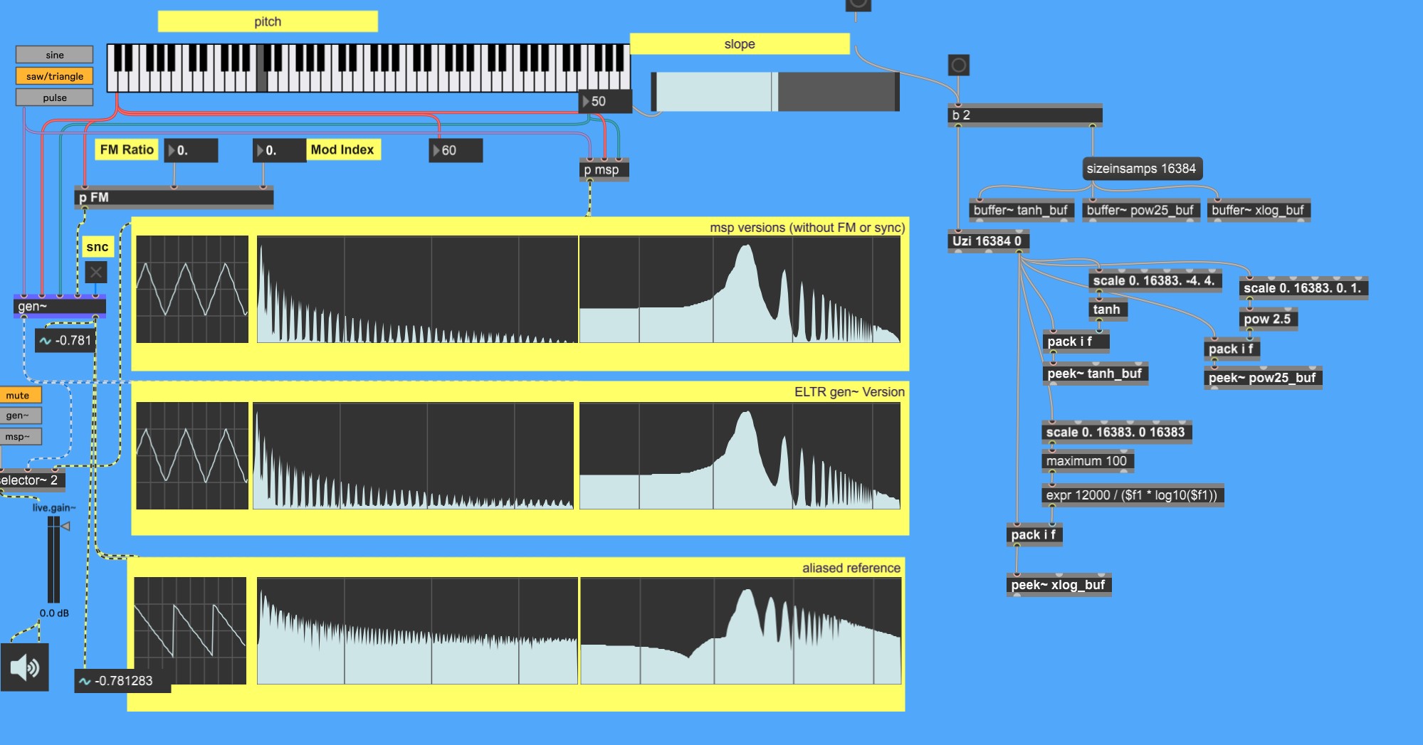
EPTR Saw and LTR Triangle Download
Someone here was able to get an EPTR saw working too, included in the following download, which also has some simpler "LTR" anti-aliased triangles. Anti-aliasing of triangle oscillators is more complicated and remains a topic for a future tutorial.
Additional examples in gen~ codebox are available on https://yofiel.com
